A cone-clamping coupling joins two shaft ends with a rigid, backlash-free connection. It is a mechanical connection rather than a flexible coupling or machine guard. The selected RINGSPANN RWK sizes below show the product’s published envelope and capacity; they are examples from one manufacturer, not universal dimensions for every cone-clamping design. For related workshop equipment, see our guides to engine hoists, workbench sizing, and garage air-compressor types.
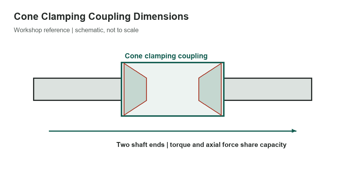
Selected RWK sizes
In the catalog, the size code corresponds to a nominal shaft-size series. Confirm the exact bore suffix in the complete ordering code: the product is configurable and a size code alone does not identify every bore or material option. The outside diameter D and axial dimensions B, L1 and L2 are in millimeters.
[gs_table id=”10846″]
The torque and axial-force figures are separate maximums. RINGSPANN states that the maximum torque applies at zero axial force, and the maximum axial force applies at zero torque. When both loads occur together, the available capacity is reduced. Bending moments also reduce the listed capacity. Do not choose a coupling by comparing only the application’s steady torque with the table’s maximum number.
Check the shaft and the load case
The catalog specifies an h8 shaft-diameter tolerance and an average contact-surface roughness range of Rz 10 to 25 micrometers for the stated ratings. It also sets a minimum shaft elastic modulus. If the shaft material, diameter tolerance or surface finish differs, ask the manufacturer to confirm the rating rather than assuming the catalog value still applies. The mating shaft ends and clamping surfaces must be clean and prepared as directed by the current installation instructions.
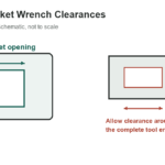
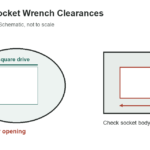
Before selecting a size, establish the maximum operating torque, startup or shock peaks, axial load, speed, temperature and any bending moment. Consider whether the driven machine can reverse or cycle frequently. Check that the shaft ends can be aligned and inserted through the complete coupling length, and that surrounding guards and supports leave room for installation and inspection. A rigid coupling does not compensate for parallel, angular or axial misalignment in the way a flexible coupling may.
The catalog presents a method for reducing the available torque or axial force when the other load is present. Treat it as a product-specific rating relationship, not a general coupling equation. If the installation uses combined loads, uncertain shaft properties, vibration, or significant bending, request a manufacturer review of the complete load case. A nominally adequate torque alone is not enough to establish an acceptable design.
Dimensions are not an installation procedure
Use D and the axial dimensions for preliminary envelope checks, then confirm the coupling drawing and the selected bore code. Do not scale the schematic to derive tolerances. Weight and screw details depend on the selected configuration, and the catalog includes additional sizes beyond those shown here. The manufacturer notes that technical details may change, so obtain the current drawing and installation instructions before machining shafts or ordering parts.
When replacing an existing connection, record both shaft diameters, usable shaft length, separation between shaft ends, keyway condition, runout and available radial clearance. Compare those measurements with the actual selected coupling drawing. If a keyless clamping connection is being considered instead of a keyed hub, check the shaft strength and the equipment maker’s approval; removing a keyway does not automatically make a retrofit suitable.
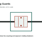
Keep guarding and isolation requirements in place while measuring or servicing rotating equipment. A coupling must be selected as part of the complete drive, including the motor, driven load and shaft supports.
Sources
RINGSPANN’s April 2026 shaft-coupling catalog supplies the selected RWK values and product-specific limitations. The manufacturer’s RWK product page describes the rigid shaft-end connection and configuration. Confirm the current drawing and installation instructions for the exact model.