A shaft coupling joins rotating shafts, but its bolts, nuts, set screws, keys, and exposed surfaces can create an entanglement or impact hazard. A coupling described as “safety” or supplied with a shroud is not automatically safe in every installation. Check the assembled machine, the coupling manufacturer’s instructions, and the applicable guarding requirements before operation.
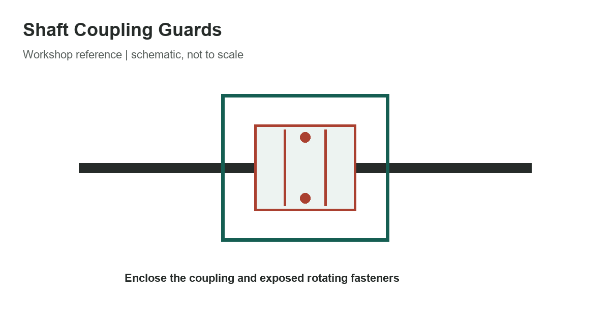
Coupling guard checklist
OSHA’s mechanical power-transmission rule states that shaft couplings must be constructed so they present no hazard from bolts, nuts, set screws, or revolving surfaces. It permits the specified fastener arrangements when bolts, nuts, and set screws are covered with safety sleeves, used parallel with the shafting, or countersunk or kept within the coupling flange. The checklist below turns those points into a field inspection sequence; it does not replace the regulation or a site-specific risk assessment.
[gs_table id=”10785″]
Inspect the complete rotating assembly
Begin with the machine stopped and isolated under the employer’s energy-control procedure. Never reach through a guard or try to check a running coupling by hand. Confirm that the guard is the correct type for the equipment and location, that it encloses the hazard, and that it is securely attached. Check for missing panels, loose mounting hardware, damaged mesh, oversized openings, sharp edges, and contact between the guard and rotating parts.
Look at every rotating projection, not only the coupling bolts. Keys, set screws, locking collars, and shaft ends may create hazards adjacent to the joint. OSHA separately addresses projecting keys, set screws, and other projections on revolving parts. Do not assume the coupling cover protects nearby shafting or a pulley. Evaluate the full drive train and nearby access points.
For a coupling whose bolts or nuts are near the outer circumference, verify the allowed guarding or fastener arrangement using the current rule and the coupling drawing. Do not machine a flange, trim a bolt, or substitute fasteners as an improvised fix. A sleeve or enclosure must be designed and retained so it cannot loosen, interfere, or become a new projectile hazard. Seek engineering or safety review when the installation is unusual or the compliant arrangement is uncertain.
After maintenance or a change
Repeat the inspection after alignment work, coupling replacement, lubrication access, guard removal, or any change in shaft speed or layout. Check that the coupling is correctly assembled, fasteners are installed and secured to the manufacturer’s torque instructions, and the shafts are aligned within the specified limits. A guard that fitted the previous coupling may not fit a replacement with a different diameter or bolt pattern.
Before restart, reinstall all guards and verify that tools and temporary supports are removed. Use the facility’s controlled restart process and observe from a safe position for abnormal vibration, noise, or contact. If a guard vibrates, rubs, or shifts, stop and correct the cause. Do not operate with a missing or defeated guard while awaiting a replacement.
Keep the inspection record tied to the machine and coupling, not just to a generic checklist. Note the asset identifier, coupling model, guard type, inspection date, defects found, corrective action, and person responsible for release. This makes it easier to notice recurring looseness or damage and prevents an old sign-off from being mistaken for approval after equipment has changed.
This page is a practical inspection aid, not legal advice or a certification that a machine complies. OSHA rules, other jurisdictional requirements, machine-specific standards, and employer procedures can add requirements. Use the current official text and consult a qualified safety professional for the installation.
Browse the reference chart library, review drive and connection sizing, and check fastener measurement basics for related shop references.
Sources
See OSHA 29 CFR 1910.219(i)(2) for shaft couplings and 1910.219(h) for projections on revolving parts. Apply the full regulation and the machine and coupling manufacturer’s instructions to the actual installation.