Ductile-iron pipe dimensions are not read from nominal size alone. A nominal size identifies a pipe-size series; it is not the measured outside diameter. Wall thickness and pressure design depend on the pipe specification, pressure class or thickness class, installation conditions, joint and manufacturer. This short selection chart shows examples from a U.S. Pipe product sheet revised in January 2019. It is a reference for reading the labels, not a current project specification.
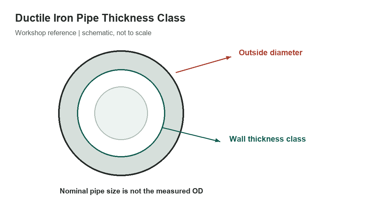
Selected thickness-class examples
The values below are the manufacturer’s stated nominal wall thickness and outside diameter for selected sizes and thickness classes. Joint-specific weights and limitations vary with the product configuration, so check the current product sheet for the joint you plan to use.
[gs_table id=”10850″]
For example, the listed 6-inch nominal pipe has a 6.90-inch outside diameter in this sheet. That difference is expected: nominal size is a designation, while the outside diameter is the dimensional value needed when checking fittings, clearances and many connection details. Use the exact manufacturer’s dimensional drawing for the chosen joint and product.
Pressure class and thickness class are not interchangeable
Pressure class is associated with rated water working pressure under the relevant standard’s assumptions. Thickness class identifies a wall-thickness series. A thickness-class number should not be read as a pressure rating, and the selected rows do not establish a safe working pressure for an installed line. The table is not a pressure-versus-size calculator and does not include surge, external load, bedding, cover, corrosion allowance, joints or operating conditions.
AWWA currently lists C150-21(R23) for thickness design and C151-23 for centrifugally cast ductile-iron pipe. The U.S. Pipe sheet shown here is dated 2019, so consult the latest product data and applicable standard before ordering or design. DIPRA’s thickness-design calculator follows the C150/A21.50 procedures, but the project engineer remains responsible for the design inputs, assumptions and selection.
Measure and specify the complete assembly
Confirm nominal size, outside diameter, wall or class designation, joint type, lining, coating and pressure conditions. Verify whether the listed dimensions refer to the spigot end, barrel or bell; the manufacturer’s sheet identifies outside-diameter tolerances and notes that weights can vary with bell construction. A fitting with the same nominal size may use a different connection geometry or dimensional series.
For field verification, measure a clean, undamaged spigot at the location specified by the manufacturer. Do not measure across a cement-mortar lining and treat that as the bare pipe outside diameter. Check ovality and coating buildup where the connection design requires it. Record the manufacturer, product series and printed revision alongside the nominal size so the data can be traced during replacement work.
Buried-pipe thickness selection also depends on external loading and laying condition, not only internal pressure. Cover depth, soil and installation support can change the required design. For a potable-water or wastewater project, confirm the project drawings and engineer’s specification, and use the current manufacturer submittal for the selected pipe and joint.
Keep pressure design, pipe dimensions and joint selection as separate checks. A barrel that meets a wall-thickness requirement may still be unsuitable if the specified joint, fitting, lining or coating is unavailable in the required configuration. Confirm the manufacturer’s current size range and allowable pressure for the exact product, and verify that all fittings and valves use compatible dimensions. The 2019 table does not establish those details.
For a replacement segment, inspect the existing pipe markings and measure the exposed end before ordering. Older systems may have product-specific dimensions or a different joint than the nearby pipe. Record the nominal size and measured outside diameter, but let the current manufacturer drawing identify the compatible gasket and connection parts.
For nearby references, compare the general pipe-size chart, the PVC pipe-size chart, and the natural-gas pipe-sizing guide. Those references cover different materials or services and do not replace ductile-iron design data.
Sources
U.S. Pipe’s USP 0550 sheet provides the selected 2019 product dimensions. AWWA lists C150-21(R23) and C151-23 as the current standards editions, while DIPRA describes the thickness-design workflow. Check current product and project documents before selecting pipe.