A metric socket needs room both to fit the fastener and to pass through surrounding structure. Its nominal opening, square drive, outside diameter and overall length describe different parts of the tool. This selected reference focuses on opening size and two useful envelope dimensions; check the current socket maker drawing before designing a counterbore or access opening.
Opening size is not drive size
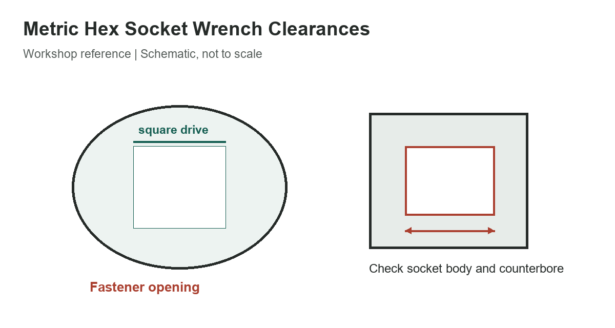
The opening fits the fastener across its flats. The square drive connects the socket to a ratchet, extension or torque tool. Those numbers are independent: a 10 mm opening can be paired with a 10 mm square drive in the selected historical data, while a 6 mm opening uses a 6.3 mm square drive.
D1 is the maximum diameter at the nut end of the socket. K is the minimum counterbore diameter stated for the matching socket row. The source also gives a radial clearance reference C of 0.762 mm for these selected examples. Do not add or subtract C again when using a drawing that already includes its clearance allowance.
Selected metric examples
Dimensions are millimeters. The table shows only four opening/drive combinations; it does not include every length, drive family or nominal opening in the original series.
| 6 | 6.3 | 9.90 | 14.47 |
|---|---|---|---|
| 10 | 10 | 15.00 | 19.124 |
| 13 | 10 | 18.80 | 23.924 |
| 19 | 20 | 30.50 | 33.76 |
4 rows
Scroll horizontally to view all columns.
For a 13 mm fastener opening with a 10 mm square drive, the selected reference lists a nut-end diameter up to 18.80 mm and a counterbore of at least 23.924 mm. That comparison is a planning clue, not a final machining tolerance. Confirm the tool actually being used, including chamfers, flats, and any protective sleeve or impact-socket wall thickness.
Check the entire access path
A socket can clear the mouth of a recess and still bind farther down. Check the full socket profile, the drive-end bulge, overall length, extension and ratchet head. If a fastener sits beside a wall or another fastener, include the tool’s approach angle and the clearance needed to remove it after tightening.
For a blind counterbore, also check whether the socket can reach the fastener without its square-drive end bottoming out. A recess that is deep enough for the nut may still be too shallow for a regular socket plus extension. Measure from the seating face to the obstruction and compare it with the actual tool stack, leaving room to engage and release the drive.
Deep sockets may reach past a protruding stud but can be wider or longer than regular sockets. Impact sockets may also have different wall dimensions than chrome hand sockets. Use the part number and manufacturer drawing for the exact construction; a nominal opening alone does not identify an envelope.
Treat legacy dimensions as a reference
The historic metric table says its values were converted from inch dimensions and points to an older socket-wrench specification. ASME B107.110-2019 is the later consolidated socket-wrench standard, but ASME explicitly cautions that dimensional data does not mean every listed configuration is a stock production size. Ask the socket manufacturer for current production dimensions and availability before finalizing a design.
The chart is not a torque recommendation. Proof torque is a tool-performance test value, not a fastener tightening target. Select tightening torque from the fastener and joint requirements, then confirm that the socket, extension and drive tools are rated for the job.
- Identify the fastener opening and square drive separately.
- Check D1 and the counterbore requirement against the exact tool.
- Include the extension and ratchet in the access envelope.
- Check current drawings, not only historic standard dimensions.
- Keep socket proof ratings separate from installation torque.
For inch-series clearance examples, see the inch hex socket clearance guide. Compare metric and SAE socket sizes, review socket-set options, or browse the size-chart library.
References
See ASME B107.110-2019 for socket-wrench requirements and confirm envelope dimensions with the socket manufacturer’s current drawing.