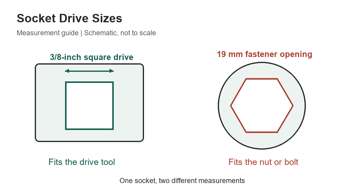
A socket has two different sizes: the opening that fits the fastener and the square drive that fits the ratchet or impact wrench. A 19 mm socket can have a 3/8-inch drive or a 1/2-inch drive. The 19 mm marking tells you about the nut or bolt; the drive marking tells you which tool can turn the socket. Measure the square across its flats, not diagonally across its corners.
For powered tools, matching the square size is only the first check. The socket and every adapter must also suit the tool type, retention system, and manufacturer’s use instructions.
Common square-drive sizes
The metric figures are exact conversions of nominal inch labels. They are not manufacturing inspection limits for a male anvil or a socket’s female recess. A working fit requires clearance, corner geometry, and retention details that cannot be reduced to a nominal conversion alone.
| 1/4 in | 6.350 | Compact drive systems; verify tool rating |
|---|---|---|
| 3/8 in | 9.525 | Common intermediate drive systems |
| 1/2 in | 12.700 | Common larger ratchet and impact systems |
| 3/4 in | 19.050 | Larger specialized drive tools |
| 1 in | 25.400 | Heavy-duty equipment; follow exact specifications |
5 rows
Scroll horizontally to view all columns.
Drive size does not establish a universal torque rating. A socket, extension, reducer, joint, and wrench can each have different limits even when their square connections fit. Use the specifications of the complete tool combination rather than a chart that assigns one maximum torque to every tool of a particular drive size.
Read the two ends of the socket separately
The fastener end may be six-point, twelve-point, external Torx, or another profile. Its size is selected for the fastener. The opposite end contains the square recess selected for the drive tool. Those two dimensions serve different purposes, so neither can reliably be inferred from the other.
A useful way to label storage is to group sockets by drive size first, then by metric or SAE fastener opening. A 10 mm socket in the wrong drive tray can look correct until you try to attach it to the ratchet. The socket sizes in order reference covers fastener-opening sequences; this page covers the connection behind them.
Measure an unidentified square drive
Clean the drive and inspect it for rounded corners, cracks, or a mushroomed end before measuring. With the tool disconnected from its power source, measure between two opposite flat faces using calipers. Compare that result with the nominal sizes in the chart. Measuring corner-to-corner gives a larger dimension and can send you toward the wrong size.
For a female recess, access and chamfers can make a quick measurement less reliable. An undamaged, correctly identified matching tool or the product’s stamped specification is a better confirmation than forcing an uncertain square into the socket. Do not hammer a mismatched connection together or grind the square to make it fit.
Impact sockets and hand sockets
Use sockets expressly rated for impact operation on an impact wrench. A shiny or black surface alone is not a dependable rating system: coatings and finishes vary. Read the product identification and instructions. A hand-tool socket that happens to fit an impact anvil has not thereby become suitable for repeated impact loading.
Check extensions, universal joints, and adapters in the same way. The fact that the socket is impact-rated does not approve an unrelated hand-tool extension between it and the wrench. Wear eye protection and follow the tool’s instructions for retention and inspection before use.
Retention is part of compatibility
Some impact anvils use a friction ring; others use a detent pin, and larger systems may require a retaining pin and ring. The socket must accommodate the specified retention arrangement and seat fully. A socket that merely slides onto the square but cannot be retained as intended is not ready to use.
One current manufacturer’s example is Tekton’s description of its impact socket lineup, which distinguishes drive sizes and retention features. It is still necessary to check your exact socket and wrench. Do not assume that a photograph of a cross-hole means every available retaining pin has the correct diameter and length.
What an adapter changes
An adapter can join two different drive sizes when its maker permits the application. It does not increase the strength of the smaller connection or turn the assembly into a single, uniformly rated tool. Added length may also reduce access and increase the chance of side loading if the tool is not kept aligned.
Before fitting a reducer, consider whether a socket with the correct drive can solve the problem more directly. If an adapter is needed, keep it within the tool maker’s requirements and inspect the entire stack. Never use an added pipe or other improvised extension unless the tool is expressly designed and approved for that use.
Choose the connection before choosing a set
- Identify the existing tool’s drive size and whether it is hand-operated or powered.
- Choose the correct fastener profile and opening size independently.
- Check whether a deep socket is needed for a projecting stud.
- Confirm that the outside socket body can reach the fastener without fouling surrounding parts.
- Match the specified retention method and inspect for damage.
Compare storage and coverage in the socket-set buying guide, or organize an existing collection with the socket-organizer guide.
Drive-system references
Tekton’s impact-socket lineup explanation gives practical product context. ISO 1174-2 identifies the separate standardized subject of driving squares for power socket tools. This nominal-size guide does not reproduce those interface tolerances or replace a controlled engineering drawing.