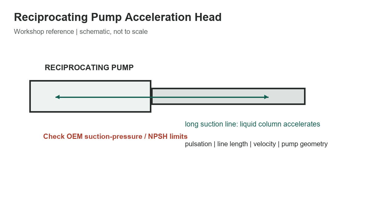
Acceleration head is the pressure head associated with accelerating and decelerating liquid in a reciprocating pump’s suction line. Unlike ordinary friction loss, it varies through the pumping cycle as the piston or plunger changes velocity. A long suction line, high mean liquid velocity, and rapid reciprocation can make this transient demand important even when average flow appears modest.
Use the equation only with its stated convention
A commonly published screening form is ha = L V N C / (K g), where L is suction-line length, V is mean liquid velocity, N is pump speed, C represents the cylinder arrangement, K is a compressibility factor, and g is gravitational acceleration. Published versions may define N, C, K, and the units differently. Do not copy a factor from one pump manual into another equation without confirming the definitions and conversion constants.
The table identifies the information to collect before estimating acceleration head. It intentionally does not supply a universal C or K lookup: pump manufacturers publish model-specific procedures, and the values are not interchangeable between pump designs or calculation conventions.
| Suction-line length | Longer liquid column raises inertial head | Use actual developed length and layout |
|---|---|---|
| Mean liquid velocity | Sets acceleration demand | Calculate from flow and actual inside area |
| Pump speed and action | Sets pulsation frequency | Use exact pump model and operating speed |
| Geometry factor C | Represents pump / cylinder arrangement | Use the pump maker's stated convention |
| Compressibility factor K | Adjusts fluid response in the model | Use the source's fluid and unit definitions |
| NPSH and suction pressure | Limits acceptable inlet condition | Confirm OEM requirement and transient margin |
6 rows
Scroll horizontally to view all columns.
Work from the actual suction geometry
Determine the liquid’s mean velocity from the flow rate divided by the pipe’s open cross-sectional area. Use the actual inside diameter, not the nominal pipe size. Record the full developed length and note reducers, pulsation dampeners, valves, branches, flexible connectors, and elevation changes. These features can affect both the transient response and the suitability of a simplified line model.
Keep units consistent throughout. The velocity and gravity units must produce the intended unit of head, and the speed term must match the equation’s convention (for example, cycles per second versus revolutions per minute). Convert deliberately and write units beside intermediate results. A numerically plausible answer can still be wrong by a large factor if cycles, revolutions, or customary/SI units are mixed.
Interpret the result as a screening estimate
Moore Pump’s technical handbook presents an equation with stated geometry and fluid factors and works through a particular triplex-pump example. That example is useful for understanding the method, but it is not a general design value for other pumps. The manufacturer may account for valve dynamics, liquid properties, line configuration, and the specific pump’s kinematics differently.
Compare the estimated transient requirement with the pump manufacturer’s allowable suction conditions and required net positive suction head. Include static head, vapor pressure, steady friction loss, temperature, altitude, fluid composition, and operating range in the complete assessment. NPSH available must be evaluated at the pump inlet under the relevant conditions; subtracting a handbook acceleration estimate from an unrelated pressure reading is not a complete design check.
Air or gas pockets, dissolved gas, vapor formation, and entrained solids can change the response. A line that works at reduced speed may behave differently near maximum speed or during startup. If the system is critical, unusually long, highly pulsating, or close to an OEM limit, request a manufacturer review or a qualified transient analysis rather than relying on a one-line formula.
Reduce risk systematically
Potential remedies include shortening or enlarging the suction line, reducing flow velocity, changing pump speed, revising the layout, or using a properly selected pulsation dampener. Each change affects the system differently. An oversized or incorrectly charged dampener is not a guaranteed fix, and suction piping still needs suitable support, valve placement, and clean liquid supply.
- Identify the exact pump and calculation convention.
- Use actual flow, inside diameter, line length, speed, and fluid conditions.
- Calculate steady friction and static head separately.
- Check OEM suction-pressure and NPSH limits over the full operating range.
- Escalate borderline or critical installations for transient review.
For related system checks, see the compressed-air pipe capacity chart, the PVC pipe size reference, and the natural-gas pipe sizing chart.
References
Read the Moore Pump technical handbook for its model-specific equation and worked example, and the Pumps & Systems overview for a discussion of acceleration head assumptions.