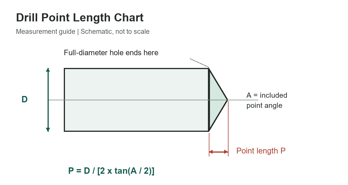
The point on a twist drill extends beyond the bottom of the full-diameter hole. For an ideal conical point, its length is drill diameter divided by twice the tangent of half the included point angle. At 118 degrees that is about 0.3004 times the diameter; at 135 degrees it is about 0.2071 times the diameter. Add that allowance when a drawing requires a specific depth at full diameter rather than a depth measured to the tip.
This chart explains the geometry of a conventional symmetric point. A split point, special grind, step drill, brad point, or flat-bottom tool can need different treatment. Use the tool drawing for a controlled machining operation.
Calculated drill-point length chart
All values below are original calculations for an ideal cone, rounded to four decimal places in inches. They are point lengths only: they do not include the required cylindrical hole depth, a breakthrough clearance, or a machine setup allowance.
| 1/8 | 0.0625 | 0.0376 | 0.0259 |
|---|---|---|---|
| 3/16 | 0.0938 | 0.0563 | 0.0388 |
| 1/4 | 0.1250 | 0.0751 | 0.0518 |
| 5/16 | 0.1563 | 0.0939 | 0.0647 |
| 3/8 | 0.1875 | 0.1127 | 0.0777 |
| 1/2 | 0.2500 | 0.1502 | 0.1036 |
| 5/8 | 0.3125 | 0.1878 | 0.1294 |
| 3/4 | 0.3750 | 0.2253 | 0.1553 |
8 rows
Scroll horizontally to view all columns.
A larger included angle produces a shorter cone for the same diameter. That is why a 135-degree drill reaches full diameter closer to the tip than a 118-degree drill. Changing the point angle therefore changes the relationship between a depth-stop setting and the usable cylindrical portion of a blind hole.
How the formula works
Call the drill diameter D, the included point angle A, and the axial point length P. Cut the cone through its centerline. One half forms a right triangle whose side opposite A/2 is the drill radius, D/2, and whose adjacent side is P. Therefore tan(A/2) = (D/2)/P, and P = D/[2 tan(A/2)].
Enter the angle in degrees when using a calculator set to degree mode. If using programming code, convert degrees to radians before calling a tangent function that expects radians. A degree/radian mistake can produce a plausible-looking number that is completely unsuitable for a depth setting.
The same unit must be used for D and P. Enter a 10 mm diameter to obtain point length in millimeters; enter 0.250 inch to obtain inches. There is no need to convert the diameter to inches first. The angle is dimensionless in the geometric relationship, so the calculation scales directly.
Worked example: a quarter-inch blind hole
Suppose an ordinary 1/4-inch drill with a 118-degree point must make a hole that is 1.000 inch deep at full diameter. The ideal point allowance is 0.250/[2 tan(59 degrees)] = approximately 0.0751 inch. The tip would therefore reach approximately 1.0751 inches below the reference surface to create that cylindrical depth.
That result is a geometry example, not permission to drill through the back of a part. First check remaining wall thickness, the tool’s actual grind, positioning error, and the drawing’s depth convention. If the entire workpiece is only 1.050 inches thick, the example cannot provide a 1.000-inch cylindrical depth with that ideal point while retaining an intact back wall.
For a 135-degree point at the same diameter, the ideal allowance is about 0.0518 inch. A depth stop left at the old setting would produce a different cylindrical depth after the drill is changed. Recheck the setup whenever the drill or its grind changes.
Hole depth, tip depth, and threaded depth
A drilled blind hole and a usable tapped hole have different depth requirements. The tap’s chamfer, chip space, thread runout, and required full threads must all fit within the prepared hole. Adding only the drill-point allowance does not automatically provide enough room for tapping. Follow the tap and drill manufacturer’s recommendations and the drawing.
The tap-drill size chart addresses hole diameter selection. It does not replace a depth plan. Keep the drawing’s diameter, cylindrical depth, thread depth, and maximum tip depth as separate requirements on the setup sheet.
Using a drill press depth stop
Establish the reference surface with the machine stopped and the work held securely. Check how the specific machine’s stop or readout measures travel. A point contacting a surface is not the same reference as the cutting lips reaching full diameter. Keep fingers away from rotating parts and remove chuck keys before starting the machine.
For a repeated noncritical job, inspect a first piece before making the full batch. Burrs, a curved surface, a previously drilled pilot hole, or a reground point can affect the practical reference. Do not rely on a rounded chart value when the part requires tighter control than the setup can demonstrate.
Common calculation mistakes
- Using the full point angle inside the tangent instead of half the angle.
- Using the radius where the formula expects diameter, or dividing by two twice.
- Treating the point allowance as the complete drilling depth.
- Mixing metric diameter with an inch depth requirement.
- Applying ideal cone geometry to a special-purpose drill tip without checking its drawing.
For workshop setup considerations, see the benchtop drill-press guide. Find related dimensional references in the size-chart library.
Tool geometry references
Guhring’s basic drill-point geometry reference identifies the tool features behind the calculation. Its basic drill-dimensions guide helps distinguish point geometry from flute and overall dimensions. Use the drawing for your particular drill whenever its geometry differs from the idealized cone shown here.