An expansion or contraction changes average velocity and creates a local energy loss in addition to friction along the pipe. The loss is commonly expressed as a coefficient multiplied by a velocity-head term. The equation is useful only when its coefficient, reference velocity, and transition geometry are defined consistently.
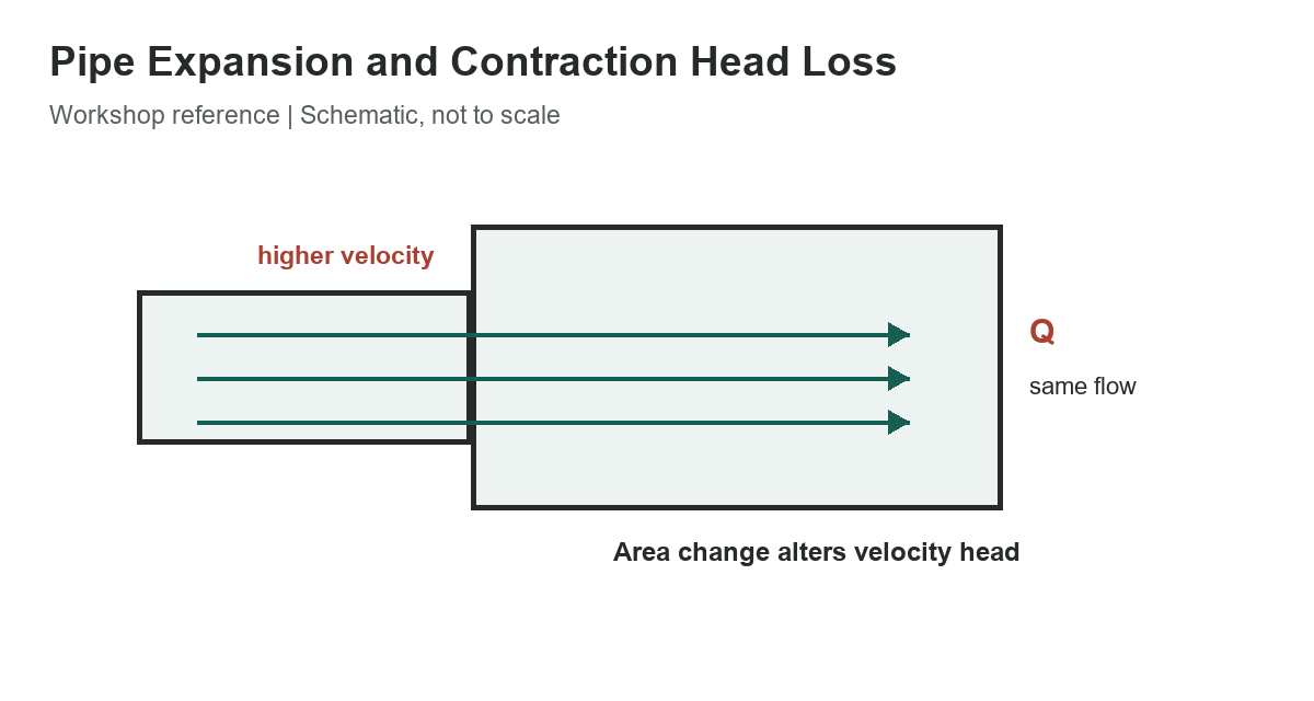
Keep the velocity reference attached to the coefficient
The selected handbook relationships are shown below. In a gradual enlargement, the inlet velocity vi is higher than the outlet velocity vo. A sudden contraction uses the velocity after the smaller section in the selected expression. The coefficients KD, KL, and KC are not interchangeable labels for one universal constant.
| Gradual enlargement | hL = KD vi^2 / (2g) | Inlet velocity vi |
|---|---|---|
| Gradual enlargement | hL = KL (vi^2 - vo^2) / (2g) | Inlet vi and outlet vo |
| Sudden contraction | hL = KC vo^2 / (2g) | Downstream velocity vo |
3 rows
Scroll horizontally to view all columns.
For the Gibson-style enlargement expression, the velocity-head difference is positive when the flow slows through the expansion. If the equation or notation in your reference uses a different section order, follow that reference rather than swapping terms by memory.
Use matching geometry and coefficient data
A gradual diffuser and an abrupt step do not have the same loss behavior. Coefficient values depend on the area ratio, transition angle or shape, upstream conditions, and how velocity is distributed. The U.S. Geological Survey describes local losses through coefficients on velocity-head differences and notes the uncertainty involved in transitions; a coefficient from an open channel or another fitting is not automatically valid for a circular pipe.
For a sudden enlargement, the Borda-Carnot relationship can be written as hL = (vi – vo)2/(2g) under its idealized assumptions. This is a separate expression with a defined geometry and assumptions; do not combine it with a handbook coefficient form unless the coefficient definition says how they relate.
As a dimensional check, if an enlargement slows flow from 3 m/s to 1 m/s, the Gibson-form velocity-head difference is (9 – 1)/(2 x 9.81), or about 0.408 m. The estimated head loss is that value multiplied by the matching KL. This is not a final result until the coefficient has been selected for the actual transition.
For the sudden-contraction expression, if the downstream mean velocity is 4 m/s, its velocity head is 16/(2 x 9.81), or about 0.815 m. Multiply by the contraction coefficient for the matching inlet-to-outlet ratio. These examples show why using the upstream velocity by habit can change the answer materially.
Separate local loss from pipe friction
Calculate straight-pipe friction separately using an appropriate friction model and pipe length, diameter, roughness, flow regime, and fluid properties. Then add local losses for the actual transitions, valves, and fittings in the system. Mixing a local-loss coefficient with a friction factor or applying the coefficient to the wrong velocity can produce a large error.
For a measured flow rate, calculate the mean velocity from flow divided by the open cross-sectional area at each section. Keep units consistent: if velocity is in metres per second, use gravitational acceleration in metres per second squared and the result is metres of head. In customary units, use feet per second and feet per second squared to get feet of head.
Check the design purpose
A short enlargement or contraction near a pump, meter, tank, or compressor can affect local pressure and flow. For critical service, transient operation, nonuniform flow, or unusual geometry, use validated engineering references or a qualified fluid-system designer. The simple equations are estimates, not a substitute for system testing or a full hydraulic model.
- Identify inlet and outlet sections and their areas.
- Use the velocity specified by the chosen coefficient definition.
- Match coefficient data to the transition geometry.
- Calculate straight-pipe friction separately from local loss.
- Keep units and head reference consistent through the system.
Compare the compressed-air pipe size chart, review natural-gas pipe sizing, and see the air-compressor guide.
References
See the USGS treatment of energy losses at expansions and contractions and its study of flow through abrupt pipe enlargements for coefficient definitions and assumptions.