A knuckle joint connects two mainly axially loaded rods through a single eye, a forked end and a pin. The pin allows limited angular movement while transferring load. The selected proportions below come from the Machinery’s Handbook figure reviewed for this reference. They are empirical layout relationships based on rod diameter D, not dimensional standards, material specifications or allowable-load ratings.
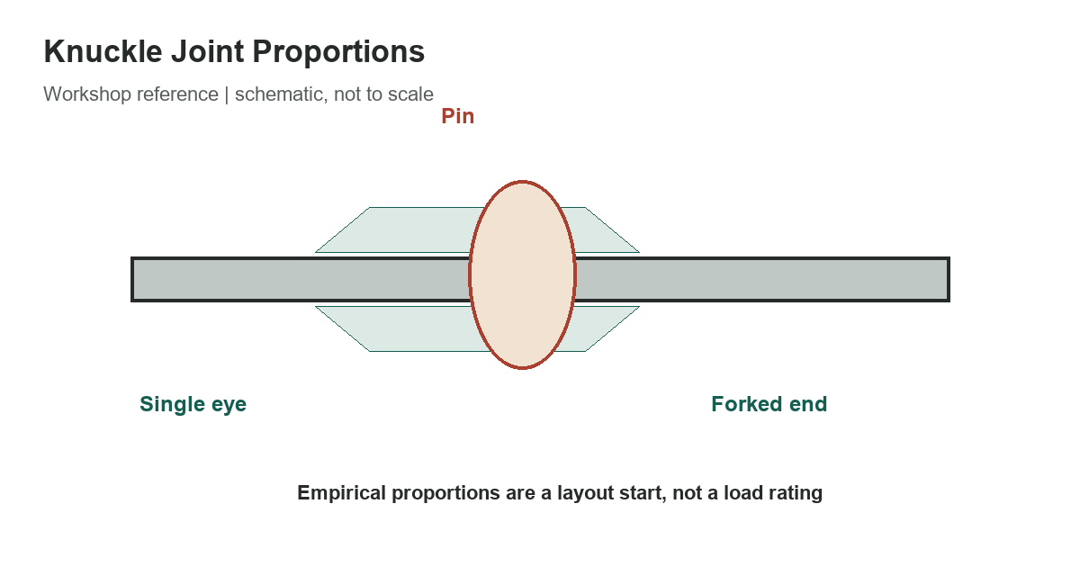
Selected empirical proportions
The letters are the figure’s own dimension labels. Because similar letters can mean different features in other textbooks or drawings, use this chart together with the matching figure and do not transfer its labels to a different joint sketch without checking the dimension arrows.
[gs_table id=”10887″]
For a 20 mm rod, the listed proportions scale arithmetically: 1.20D becomes 24 mm, 0.75D becomes 15 mm, and 2D becomes 40 mm. These are preliminary layout values only. Rounding to a manufacturable size, selecting pin clearances, choosing a split pin or collar, and detailing the pin head all require the actual drawing and design requirements.
Understand the load path
The rod eye bears against the pin, and the pin transfers load into the two fork legs. A complete design must consider more than matching proportions. Potential checks include rod tension, eye net-section tension, eye shear and bearing, fork tension, fork shear and bearing, pin double shear, pin bending, stress concentration, fatigue and retention. The relative importance depends on geometry, fit, materials, load direction and whether the pin can bend or rotate.
University machine-design notes describe these failure modes and treat empirical proportions as a starting point followed by analytical checks. Their particular equations depend on assumptions about uniform pressure, material, clearances and support. Do not apply a formula from a different joint geometry or assume a proportioned joint is automatically safe for a stated force.
Use proportions as a drawing aid
Begin with the required rod diameter D only after its tensile stress and service conditions have been established by the responsible designer. Use the proportions to sketch an initial eye, fork and pin arrangement, then check that the eye fits between the fork legs with suitable running clearance and that the pin can be assembled and secured. Ensure the joint’s permitted angular movement does not cause interference with adjacent structure.
Next calculate the stresses and compare them with design allowables appropriate to the material, manufacturing process, loading, environment and applicable code. Consider shock, cyclic load, corrosion, wear, lubrication, temperature and misalignment. A pin under bearing load can also experience bending; treating it as pure double shear may miss a governing failure mode. Fatigue or fracture-critical applications need an appropriate qualified analysis.
Specify the pin material, heat treatment, surface finish, fit, lubrication and retention method. Avoid substituting an ordinary bolt for a purpose-designed pin without reviewing the load path and bearing surfaces. Inspect the pin and holes for wear, cracks, deformation and looseness at the interval required for the equipment. Replace damaged retainers and do not keep operating a joint with visible play beyond its service limit.
This chart omits the adjacent disk-clutch equation on the original handbook page because it is unrelated to knuckle-joint layout. The chart also does not claim that the listed ratios agree with every textbook’s conventional proportions; alternate references use different symbols and values. Follow the governing drawing, specification and engineering approval for the actual machine.
For related mechanical references, see our bolt dimensions chart, engine-hoist guide, and garage workshop guide. Those pages do not provide knuckle-joint capacity or replace the design checks described here.
Sources
The selected lettered ratios were transcribed from the visually reviewed Machinery’s Handbook knuckle-joint figure. VSSUT and engineering lecture notes support the joint’s eye-fork-pin load path and the need to check multiple failure modes. Final dimensions and capacity require a qualified design for the actual application.