Wall thickness is one of the first decisions in injection-molded part design because it affects filling, cooling, shrinkage, cycle time, appearance, and dimensional stability. A material chart can help establish an initial scale, but it cannot select a production wall by itself. Resin grade, flow length, gate location, mold temperature, machine capability, geometry, and performance requirements all change the result.
Read ranges as design guidance, not limits
The table gives selected illustrative ranges published in Protolabs’ design guidance for common resin families. These ranges are useful for an early review and comparison, but they are not guaranteed minimum and maximum wall thicknesses for every grade, tool, or supplier. Confirm the current source document, exact resin, and molding partner before releasing a design.
| ABS | 1.14-3.50 | Supplier guide range; geometry and grade matter |
|---|---|---|
| Acetal (POM) | 0.64-3.05 | Check flow length, shrinkage, and grade |
| Acrylic (PMMA) | 0.64-3.81 | Appearance and stress sensitivity matter |
| Nylon (PA) | 0.76-2.92 | Moisture and grade affect dimensions |
| Polyethylene (PE) | 0.76-5.08 | Large range is not a uniform-wall target |
| Polypropylene (PP) | 0.64-3.81 | Validate flow, sink, and part stiffness |
| Polystyrene (PS) | 0.89-3.81 | Confirm impact grade and flow path |
7 rows
Scroll horizontally to view all columns.
Use current resin data for the exact grade: broad family names can conceal major differences in flow, shrinkage, reinforcement, and processing behavior. Treat any general range as a starting point and confirm it with the supplier and production molder.
Prefer a consistent nominal wall
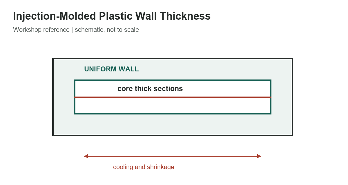
As a starting rule, keep adjoining walls reasonably uniform so the part fills and cools predictably. Abrupt thick-to-thin transitions can create uneven flow, differential shrinkage, sink marks, voids, warpage, or residual stress. Use gradual transitions and radii where the geometry permits. A uniform nominal wall is a starting objective, not a claim that every feature can have identical thickness.
Where a design needs stiffness, consider ribs, gussets, or a supported section instead of simply adding a large solid mass. Rib thickness and height must be designed relative to the nominal wall and resin behavior; thick rib intersections can telegraph through a visible surface. A core-out can reduce a heavy section, but it must preserve the required load path, sealing surface, and manufacturability.
Check flow length and feature interactions
A thin wall that works near a gate may not fill reliably at the far end of a long flow path. Flow length, melt temperature, pressure, venting, gate size, and resin viscosity interact. Long, narrow ribs, bosses, threads, living hinges, and large flat panels each introduce their own constraints. Avoid treating the table’s lower value as a universal minimum without a mold-flow and supplier review.
Wall changes also affect cooling time because thick areas retain heat longer than thin sections. That can increase cycle time and promote sink or internal voids. If a thick feature is essential, discuss gate and cooling strategy with the molder early; changing nominal thickness late can affect tooling, fit, and the part’s structural performance.
Choose the exact resin before finalizing
“Nylon,” “ABS,” and “polypropylene” each cover grades with different fillers, impact modifiers, flow properties, shrink rates, and moisture response. Reinforcement can improve stiffness while increasing anisotropy and warpage. Flame-retardant or recycled-content grades may have different processing behavior. Use the manufacturer’s data sheet for the exact grade and confirm whether its quoted values are typical or guaranteed.
For a production part, send the molder the material designation, wall map, cosmetic surfaces, tolerances, operating temperature, loads, and annual volume. Ask for feedback on gate position, fill, venting, cooling, draft, and expected shrinkage. Prototype the critical features and validate dimensional and mechanical performance in the intended environment.
- Use the ranges only for early concept sizing.
- Keep nominal walls consistent and transition gradually.
- Core out thick sections where function allows.
- Check flow length, ribs, bosses, gates, venting, and cooling together.
- Validate the exact grade and tool with the production molder.
Compare PVC material and size references, read about running-board material choices, and review the garage-door construction guide for other material-selection contexts.
References
Protolabs’ mouldability guide provides the selected starting ranges and uniform-wall discussion. Confirm grade-specific processing requirements with the resin maker, such as the BASF Ultramid design guidance.