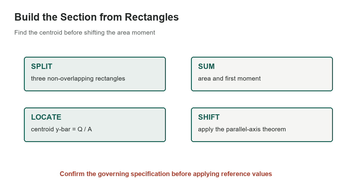
A built-up section’s second moment of area depends on the shape and the axis. This worked example breaks a stepped section into three non-overlapping rectangles, calculates each part about a common base, then shifts the result to the composite centroid. The dimensions come from one historical handbook figure; the component values below are independently recalculated rather than copied from its rounded table.
[gs_table id=”11384″]
Set the geometry and axis
The base reference axis DE is horizontal along the bottom of the example. Rectangle A spans 0 to 0.125 in, B spans 0.125 to 0.625 in, and C spans 0.625 to 1.500 in. Their widths are 1.500, 0.531, and 0.219 in. These spans touch but do not overlap, so each piece is counted once.
For a rectangle of width b from height h to h1 above the base axis, area is A=b(h1-h), first moment is Q=b(h1^2-h^2)/2, and the area moment about DE is I_DE=b(h1^3-h^3)/3. The formulas follow by integrating the rectangle’s area over the vertical coordinate. Keep inches for every dimension; the results then have units of square, cubic, and fourth-power inches.
Locate the centroid
Add the component areas to get A=0.644625 in^2 and add their first moments to get Q=0.3148828125 in^3. The composite centroid above DE is y-bar=Q/A, approximately 0.48847 in. This is the neutral-axis location for a homogeneous section in the simple beam-bending setting; different materials or composite action require a transformed-section method.
The parallel-axis theorem states that an area moment about a parallel axis equals the centroidal moment plus area times the squared distance between axes. Equivalently, the centroidal moment can be found by subtracting A times y-bar squared from the moment about DE. MIT OpenCourseWare derives the theorem for composite sections and explains summing each part’s local contribution.
Recalculate before rounding
Using the labeled component dimensions, the total moment about DE is about 0.2723965 in^4. Shifting to the centroid gives I_x approximately 0.1185843 in^4. The printed handbook table rounds component areas and moments before showing its final result, so recalculating from those rounded totals can produce a slightly different last digit. Preserve precision through the calculation and state how the result was rounded.
This example is a geometry calculation, not a beam rating. Bending capacity also depends on section modulus, material properties, supports, load position, connections, stability, and the governing design code. Do not use the result alone to size a shelf, lift point, vehicle part, or structural member.
Connect the calculation to the actual build
Use measured dimensions from the actual section and identify whether gaps, overlaps, fillets, holes, or joined materials affect the cross-section. For a nonrectangular shape, divide it into suitable simple regions or use an approved section-property method. Verify the axis direction: a section can have very different moments about its horizontal and vertical centroidal axes.
For practical garage construction, see the site’s workbench sizing guide, garage workshop planning guide, and workbench-top material guide. Those pages address workspace choices, not structural calculations or load ratings.
A reusable calculation sequence
For another built-up shape, make a sketch with a clearly named reference axis and divide the section into non-overlapping regions. Create a row for each region with its width, vertical limits, area, first moment, and inertia about the common reference axis. Check that the areas reconstruct the full cross-section and that the units are consistent before summing. Then divide total first moment by total area for the centroid and apply the parallel-axis relationship to shift the total inertia to that centroidal axis.
As a reasonableness check, the centroid must lie within the section’s vertical extent, and the centroidal inertia must be positive and smaller than the inertia about a parallel axis displaced from the centroid. Recalculate with unrounded dimensions if the result will be used in a later engineering calculation. For an asymmetric section, repeat the work for the perpendicular axis rather than assuming the two values are alike. Have a qualified engineer verify the model and load case before using any section property for design.
Sources: Machinery’s Handbook, 31st edition, selected original page, MIT OpenCourseWare: composite-section parallel-axis theorem