A riveted joint does not have one universal “strength.” The load can be limited by a rivet shearing across one or more planes, a plate tearing through its net section, bearing around a hole, or a more complex failure path. The table gives basic mechanics relationships for a simple repeating pitch so you can identify what a calculation must check. It is not a design value, safety factor, or approval to use a joint in a structure.
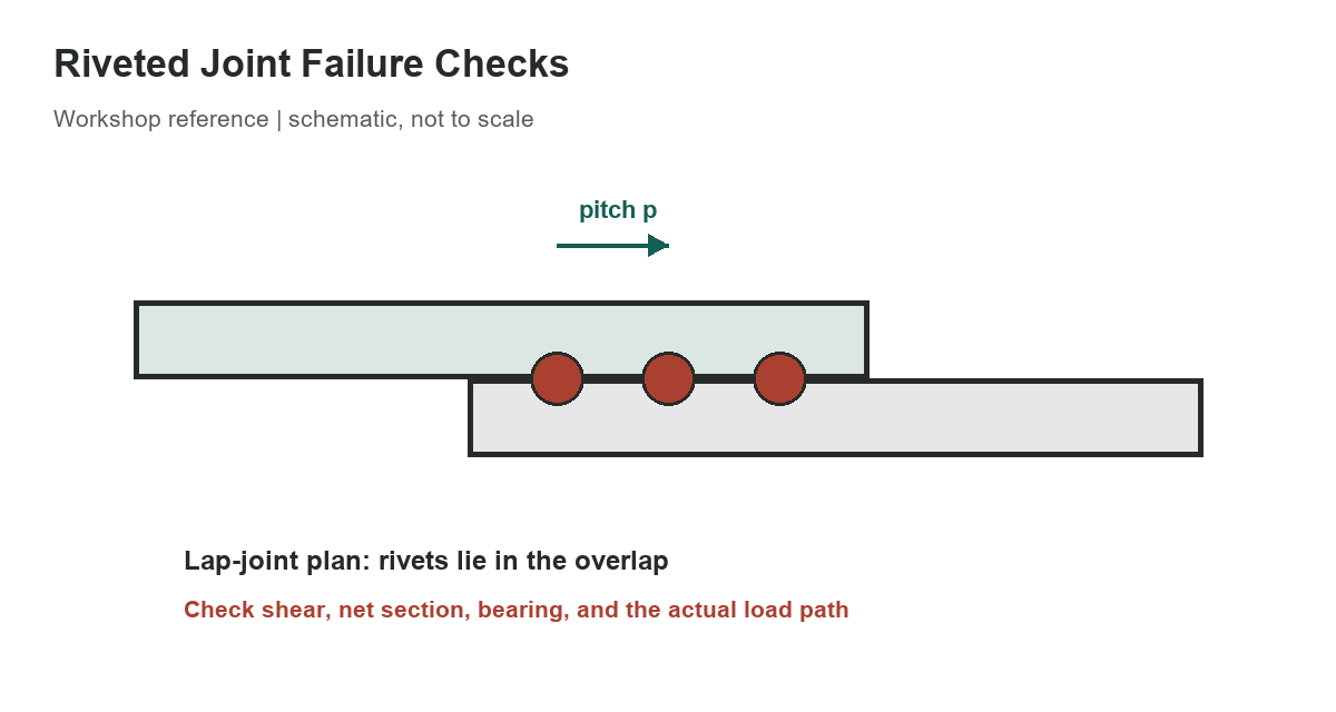
Basic resistance relationships
Use consistent units. In the expressions below, nᵣ is the number of rivets on the critical section, nₛ is the number of shear planes per rivet, dᵣ is the rivet shank diameter, dₕ is the hole diameter, p is the pitch along the load direction, and t is the plate thickness. The symbols Fᵥ, Fₜ, and Fᵦ represent the applicable shear, tensile, and bearing stress inputs for the materials and design method.
[gs_table id=”11126″]
Find the governing failure mode
For a single-riveted lap-joint pitch, rivet shear is the shear area multiplied by its applicable stress input. A rivet has one shear plane in a simple lap joint; a double-cover butt joint can create two planes, but load sharing and the cover-plate arrangement must be modeled correctly. The number of shear planes is not simply the number of plates visible in a sketch.
For one plate row with a single hole through a pitch, the net tensile area is approximately (p − dₕ)t. Bearing uses the projected area dᵣt for each rivet sharing the load. These expressions omit edge tear-out, block shear, eccentricity, prying, fatigue, corrosion, installation condition, and interactions among failure paths. Multi-row joints require a drawing-based section through each plausible path; the simple minimum shown in the table is only a first screen for the idealized case.
Worked arithmetic, not an allowable load
Suppose one idealized rivet has a 5 mm shank, one shear plane, and an assumed shear stress input of 150 N/mm². Its shank area is π(5 mm)²/4 = 19.63 mm², so the arithmetic product is about 2.95 kN. This example only demonstrates the units and area calculation. The assumed stress is not a recommendation, and the result ignores the plate checks, actual rivet material, installation, design factors, and applicable code.
A real connection assessment needs the correct rivet specification and condition, hole and plate dimensions, load direction, number and spacing of rivets, eccentricity, temperature, environment, fatigue duty, and governing design standard. Historical handbook equations are explanatory mechanics, not a substitute for a qualified engineer’s analysis. NASA’s fastener manual discusses fastener and rivet selection, while bridge evaluation requirements use formal bearing-type connection procedures for riveted structures.
Pitch is measured center-to-center along a rivet row; the transverse spacing between rows is a separate dimension. A hole diameter can differ from the rivet’s nominal shank diameter because of the specified installation clearance or process. Use the actual drawing and material specification for both instead of substituting a nominal fastener size into every term. For a staggered layout, the critical net-section width may follow a diagonal path and can differ from a straight pitch minus one hole.
In practical review, draw each plausible failure path through the connected plates, mark the number of rivets and shear planes crossed, and calculate the matching resistance with the correct material data. Then check the remaining section, bearing, edge distance, and any applicable block-shear or fatigue criteria. The smallest of the relevant resistances may govern, but a formula list cannot decide which paths or factors the governing code requires.
For neighboring geometry references, see our knuckle-joint proportions chart, bolt and screw clearance-hole chart, and socket drive size guide. Each covers a different dimension or connection question.
References
- NASA RP-1228 covers fastener design criteria and rivet selection.
- AASHTO’s Manual for Bridge Evaluation describes formal evaluation of riveted connections.
- The original handbook page illustrates rivet shear, plate tearing, and crushing paths; its variables must be mapped to the actual joint drawing before use.