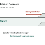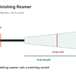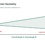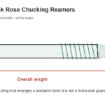
A taper-pin reamer finishes a tapered hole for a matching pin. The dimensions below are selected examples for the straight- and spiral-flute, squared-shank style shown in the source. They are reference dimensions, not a substitute for the drawing, pin specification, or toolmaker’s current catalog.
[gs_table id=”11247″]
Read the size and taper together
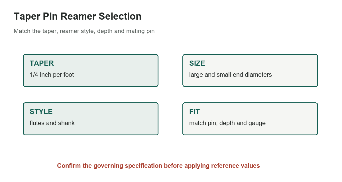
The source states a taper of 1/4 inch per foot. That is a diameter change along the axial length, not an angle: over 12 inches, the diameter changes by 0.250 inch. Over one inch of axial travel, the corresponding change is 0.02083 inch. Do not confuse this with the included angle printed for another reamer family on the same page.
The large-end and small-end diameters shown in the table are reference diameters for the listed reamer number. The exact finished hole also depends on how deep the reamer enters the work. A taper pin seats at a particular axial position, so a small depth change alters the contact and protrusion. Use the actual pin and drawing to establish depth and fit.
Check the tool style and its notes
The handbook page distinguishes straight flutes, left-hand spiral flutes and high-spiral reamers. The table here covers the first style grouping only and keeps a subset of sizes. Shank and square dimensions, flute count, material and tolerances are not included in this compact lookup. Confirm those fields in the tool supplier’s specification before ordering or programming a machine.
Flute style affects chip handling and cutting behavior. A tool intended for a through hole may not be suitable for a blind hole, and a squared shank is not interchangeable with a round-shank version simply because the nominal reamer number matches. Identify the hand, flute, shank, cutting material and workpiece before comparing catalog listings.
Plan the hole before reaming
Reaming is a finishing operation, not a way to establish a badly misplaced or undersized pilot hole from scratch. Check the recommended predrill size, alignment, stock allowance and workholding from the toolmaker. Secure the work and select a compatible cutting fluid and speed for the material and reamer design. Avoid relying on a generic speed value when the tool maker publishes a material-specific recommendation.
Keep the reamer aligned with the hole axis and avoid forcing it through a bind. Excessive feed, poor chip evacuation, runout or a damaged cutting edge can produce a bell-mouthed, oversized or rough hole. Inspect the finished taper with the specified gauge or matching pin, and confirm engagement and flushness against the design requirement.
Use the right fitment reference
ASME B94.2 covers reamer nomenclature, types, sizes and tolerances; ASME lists its 1995 edition as reaffirmed in 2025. ASME B18.8.2 covers dimensional and general data for pins, which is a different component question. Check the governing drawing and current standard rather than assuming one chart controls both tool and fastener dimensions.
For neighboring shop references, see the bolt and wrench size chart, lug-nut socket chart, and SAE wrench size chart. Those pages help identify fastener and wrench sizes; they do not specify the taper, hole depth or reamer tolerances for this operation.
Verify before production
Before cutting a critical hole, check the exact reamer number, flute direction, shank style, tolerance class, work material and mating pin. Confirm the source revision and gauge method, then test the process on a representative setup. A nominal diameter match alone does not prove that the taper, contact length or pin projection will meet the assembly requirement.
Use this selected chart to narrow a lookup, then consult the reamer manufacturer and applicable drawing for the complete dimensional notes. Reamers are cutting tools; follow the machine maker’s guarding, workholding and operating instructions. Do not hold the work by hand near a rotating tool.
Sources: ASME B94.2, ASME B18.8.2, and the visually reviewed Machinery’s Handbook page.