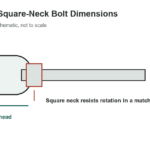
A T-head bolt is fitted through a slot and turned so its head bears across the opening. Correct selection depends on more than thread diameter: the body, head width, head length and head height must match the actual slot and clamping arrangement. The dimensions below are selected inch-series T-head product examples from AFT Fasteners, which identifies ASME/ANSI B18.5.2 as its dimensional reference.
Selected inch-series examples
The table shows the body diameter and two head dimensions as maximum/minimum values in inches. It does not include every available length, head radius, thread length, material or finish. Repeated thread sizes can appear with several bolt lengths while retaining the same basic head dimensions.
[gs_table id=”10862″]
AFT’s examples identify Grade 5 material properties with SAE J429, but the dimensional rows alone do not verify the grade or coating of a bolt you already own. Check head markings, product documentation and the full part specification. ASME B18.5-2012 was reaffirmed in 2023; its scope includes several inch-series round-head bolt types, so confirm that the purchased item is the specific T-head style required.
Measure the slot before ordering
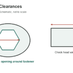
Measure the slot opening at its narrowest point and inspect its undercut, depth, end shape and available turning clearance. Compare those features with the complete bolt drawing, not only the nominal thread. The head must pass through the insertion opening and then bear securely after rotation. If the head is too wide or tall, it may jam; if too small, it may not provide the intended bearing surface.
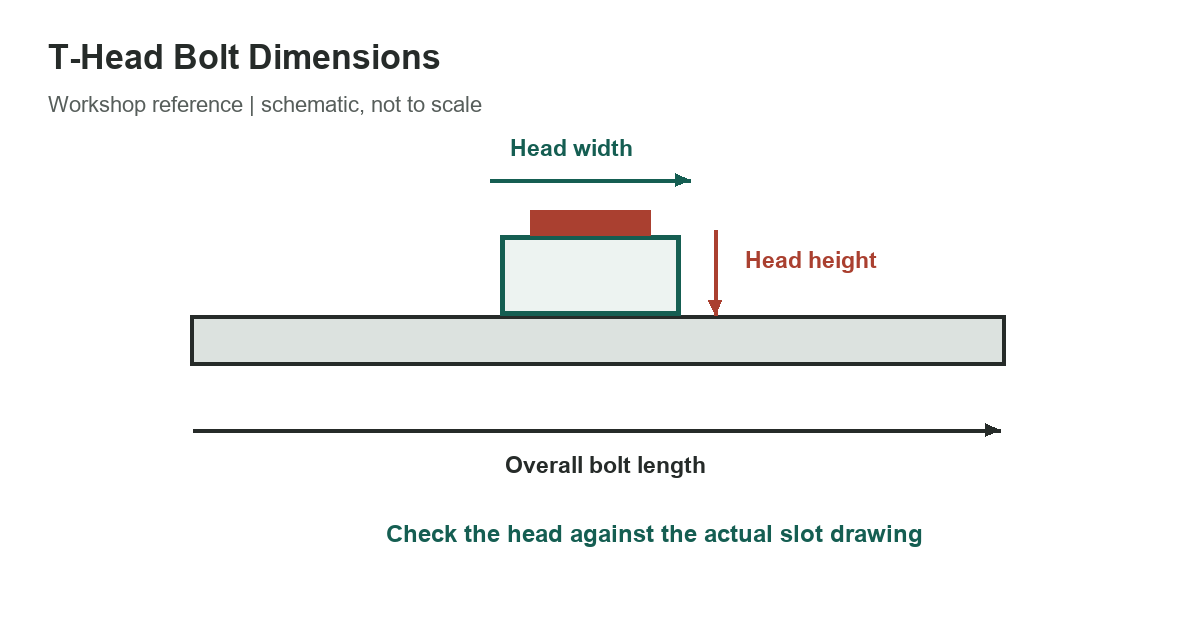
Measure a bolt head across parallel faces, not across corners, and record both dimensions and the measurement location. Check head length along its long axis and head width across its short axis. Head height controls vertical clearance below the work surface. The T shape may use a small corner radius or chamfer; inspect the manufacturer drawing for its actual profile and tolerances.
Do not infer a slot standard from a bolt that happens to fit. Machine-table slots, pipe clamps, fixture plates and extrusion profiles can use different geometries. A nominally matching thread does not establish that the head is compatible with the table or that the bolt has adequate strength. Replace hardware with the specified product or have the responsible designer approve an alternative.
Check length, material and load separately
Specify thread size and series, bolt length, head style, material grade, finish and any required certification. Confirm that the threaded length gives adequate nut engagement without bottoming out, and that the head can rotate without contacting the workpiece. The selected dimensional examples are not load ratings, installation torques or proof-load values.
Clamping force depends on the bolt material, thread condition, lubrication, nut, fixture geometry and tightening method. Use the equipment maker’s torque or clamping instructions when provided. For a lifting, structural or pressure-retaining assembly, do not substitute a shop T-head bolt based only on matching dimensions.
Maximum/minimum pairs in a dimensional table describe a permitted size range, not two alternate nominal sizes. Keep their order clear when comparing a measured bolt: for example, a body diameter listed as 0.515/0.483 inches means a maximum of 0.515 and a minimum of 0.483 inches in this supplier’s notation. Confirm the drawing’s datum and tolerance convention if a feature is near either limit.
Thread callouts also carry more information than diameter alone. In 1/2-13, the nominal diameter is one-half inch and 13 is the number of threads per inch; the thread series and class must still suit the mating nut. Bolt length is measured according to the product’s specified convention, usually from the bearing surface under the head to the end. Check the drawing rather than adding the head height to the nominal length.
Slot edges should be free of burrs and damage, and the bolt should bear flat after it is turned into position. A damaged slot can prevent proper seating even when the nominal dimensions match. Do not force a head into an opening or grind the bolt to make it fit; that can remove material from a loaded feature and invalidate the product specification.
For related fit references, see the bolt and wrench-size chart, metric socket-head cap-screw dimensions, and American wrench-size chart. These cover different fastener features and do not establish T-slot compatibility.
Sources
AFT Fasteners supplies the selected product dimensions and identifies the referenced dimensional specification. ASME’s B18.5 listing confirms the standard edition and scope. Check the complete product drawing and material specification before use.