A formed hex screw can resemble a conventional metric hex cap screw, but similar appearance does not make the products dimensionally or functionally interchangeable. This selected reference summarizes six head-size examples from ANSI/ASME B18.2.3.2M-2005. ASME now describes that edition as historical reference only, so use it to interpret an older drawing or part, not to approve a new design or purchase.
[gs_table id=”11372″]
What the historical table measures
The table lists nominal thread size and pitch, body diameter limits, width across flats, head height, and washer-face diameter. All values shown are millimetres. Width across flats is the wrench-engagement dimension; head height and the washer-face dimensions describe different parts of the head and should not be substituted for one another.
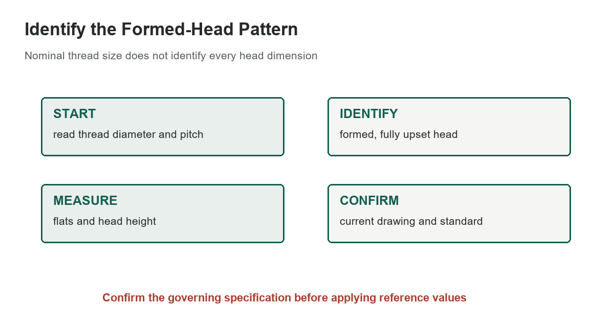
Formed hex screws have cold-formed, fully upset, non-trimmed heads in the cited standard. That manufacturing description matters when comparing the table with a machined or differently standardized hex screw. The handbook page also says not every size and option is necessarily a stock item.
Handle the M10 exception carefully
The original page marks an M10 screw with 15 mm across flats as a special, nonstandard option. It says the ordinary M10 formed hex screw supplied is 16 mm across flats unless the 15 mm option is specifically ordered. The table here therefore uses the ordinary 16 mm row. Do not choose a wrench solely from an M10 thread label or infer that the special variant is commonly stocked.
For a current part, match the complete standard, thread pitch, material or property class, length, head form, and manufacturer part number. A dimensional match alone says nothing about strength, coating, thread engagement, or suitability for a joint.
Use current product documentation
ASME’s listing states that B18.2.3.2M-2005 is no longer an American National Standard or an ASME-approved standard and is available for historical reference. If an old drawing cites it, ask the responsible engineer or manufacturer whether the legacy part is still approved for the application. For new work, specify a current product standard and verify the supplier’s drawing rather than silently substituting a superficially similar fastener.
Fastenal’s metric fastener guide distinguishes standard-specific hex cap screw dimensions and identifies the metric hex cap screw family under B18.2.3.1M alongside ISO and DIN designations. That comparison helps explain why a formed hex screw chart should not be treated as a general-purpose metric hex-bolt chart.
Compare related fastener references
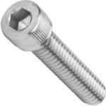
A socket-head cap screw uses a different head form; see the site’s metric socket-head cap screw chart for that separate product. The hex lag screw dimensions and bolt and wrench-size chart cover other fastener patterns. None replaces the governing standard or a current manufacturer’s specification.
Before identifying a replacement
Begin with the complete marking or drawing callout, not a wrench measurement alone. Record the nominal diameter, pitch, length, head form, material or property class, finish, and any specified standard. Measure the existing head across opposing flats and its height, but treat those observations as identification clues rather than proof of an exact replacement. A worn or coated head can also distort a caliper reading.
If the fastener is part of a safety-critical or load-bearing joint, do not substitute from a dimensional chart. Confirm the original part number and the responsible design authority’s requirements. A supplier can help identify a matching product, but the application owner must approve material, strength, corrosion protection, and thread engagement. Keep the legacy drawing and the confirmed replacement specification together so the next maintenance cycle does not have to repeat the identification.
Sources: Machinery’s Handbook, 31st edition, metric formed-hex-screw Table 2, printed page 1715 (historical standard), ASME B18.2.3.2M-2005: Metric Formed Hex Screws, Fastenal metric fastener standards and dimensions