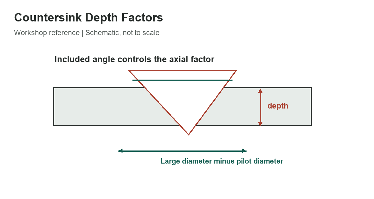
A countersink angle converts a diameter difference into axial depth. For a straight-sided truncated cone, depth is measured from the surface to where the cone reaches the pilot-hole diameter. The calculation uses the difference between the large opening and the pilot hole; using the full opening diameter would assume a sharp point at zero diameter.
Use the included angle
Let D be the large countersink diameter, d the pilot-hole diameter, and alpha the included tool angle. The ideal axial depth is z = (D – d) / (2 x tan(alpha / 2)). A table factor F = 1 / (2 x tan(alpha / 2)) gives the shorter form z = (D – d) x F. Keep all diameters and depth in the same units.
Selected factor examples
The table shows four angles and the calculated depth for a 6 mm difference between the large and pilot-hole diameters. Factors are rounded to four decimal places, so depths are approximate. These are geometric examples, not a tool-setting prescription for a specific fastener or production part.
| 82 | 0.5752 | 3.4512 |
|---|---|---|
| 90 | 0.5000 | 3.0000 |
| 100 | 0.4195 | 2.5170 |
| 120 | 0.2887 | 1.7322 |
4 rows
Scroll horizontally to view all columns.
At 90 degrees, the factor is 0.5000, so a 6 mm diameter difference gives an ideal depth of 3.000 mm. At 82 degrees, the factor is 0.5752, giving about 3.451 mm for the same diameter difference. The smaller included angle requires more axial depth to create the same radial enlargement.
Start from the drawing and fastener
Choose the specified countersink diameter and included angle from the fastener standard or engineering drawing. Do not infer the angle from the screw head alone: inch and metric fastener systems can specify different geometries, and a mismatched tool can leave the head proud or cut away too much material. ISO 10642:2026 covers a defined metric hexagon-socket countersunk screw family; use its current dimensions when that is the specified fastener.
Harvey Tool lists combined drill/countersink tools with several included angles, including 82, 90 and 100 degrees. The product’s actual angle, tip shape, flute geometry and available size still need to match the job. A pilot-hole diameter, a fastener-head diameter and a drawing tolerance are all part of the fit.
Limits of the ideal calculation
The formula assumes a centered, perfect cone. A real tool has a tip truncation, runout, edge break, wear and a measurement tolerance. The pilot hole may also be off-center or have a burr. These effects change the measured seat and can make a calculated depth differ from the finished countersink.
Measure the pilot at the surface where the conical cut begins, especially when the bore already has a chamfer or counterbore. If the part has a coating or a specified edge break, include that feature in the drawing interpretation rather than treating the surface as a sharp, ideal intersection.
For a controlled fit, cut a trial feature in scrap of the same material, check the fastener seating and inspect the specified diameter or depth. Use a stop, countersink gauge or measurement method appropriate to the drawing. In production, the drawing’s controlling dimension and tolerance take precedence over a rounded factor table.
For example, a 6 mm difference between the large opening and pilot diameter at 90 degrees gives a 3 mm ideal depth. If the pilot is 4 mm and the mouth is 10 mm, the radial increase is only 3 mm; the full 10 mm mouth diameter is not the depth input. This distinction avoids doubling the intended cut depth.
- Use the specified included angle and large diameter.
- Subtract the pilot-hole diameter before multiplying by the factor.
- Keep inch and metric units consistent.
- Account for tool tip, runout and part tolerances.
- Verify seating on a representative sample.
For related shop references, use the benchtop drill-press guide, review the tap drill-size chart, and browse the reference chart library.
References
See ISO 10642:2026 for a defined metric fastener family and Harvey Tool’s current combined drill/countersink range for available included angles.