A core drill enlarges an existing hole while retaining a pilot-like cutting action, but selecting one by diameter alone can leave too little flute length or too much overall reach. This compact chart pairs selected fractional diameters with the flute length F and overall length L shown for three- and four-flute designs. The dimensions come from ANSI/ASME B94.11M-1993, which ASME still lists as in effect on stabilized maintenance. Confirm the exact current tool drawing before ordering.
[gs_table id=”11401″]
Keep the dimensions separate
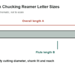
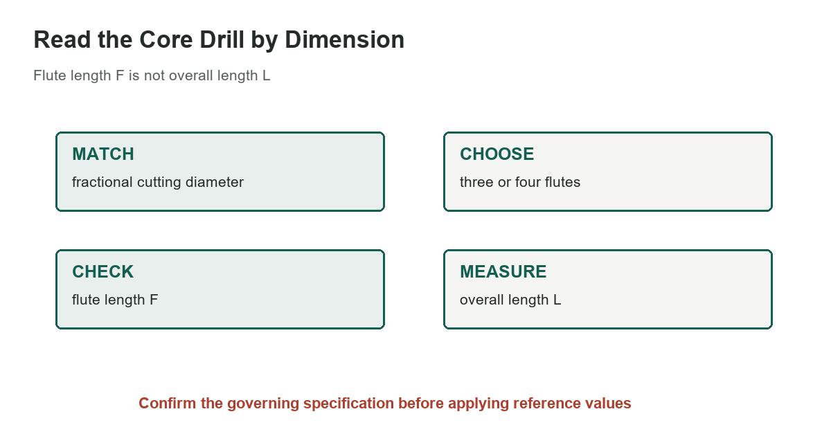
The source drawing labels D as drill diameter, F as flute length, and L as overall length. F describes the fluted cutting portion; L includes the complete tool from the tip to the end of the shank. A drill can have the correct diameter but still be unsuitable if its flute length does not cover the work or its overall length collides with a fixture or machine enclosure.
The chart keeps only eight selected combinations with values printed in the source. A size that appears twice has both three- and four-flute listings. A missing row in this compact selection does not mean that a tool is unavailable; it means the combination was not included here. The source table uses ellipses for combinations without a listed length, and those marks are not zero dimensions.
Check the point sketch and shank
The page shows separate point sketches for smaller diameter ranges. One drawing depicts a 118-degree point, while the other labels a chamfered form and its own dimensional note. Do not apply the chamfer note to every size or assume the two sketches describe the same tip geometry. The page also states that the nominal shank size matches the nominal drill size for this straight-shank series; inspect the maker’s drawing and actual shank before relying on that convention.
Flute count, point form, material, and cutting geometry affect chip evacuation and use. This chart does not state permissible material, feed, speed, or a finished-hole tolerance. Use the drill maker’s recommendations for the work material, pilot hole, coolant, and machine.
Distinguish this tool from nearby drill references
A straight shank is held in a chuck or suitable holder; a taper shank seats in a matching machine taper. The site’s selected taper-shank core drill chart covers a different mounting style. The drill-point length chart concerns point geometry, while the benchtop drill press guide addresses machine selection. Match the reference to the feature you are measuring.
Verify the actual tool before a cut
Compare the marked diameter, flute count, shank, point, F, and L with the order and drawing. Check that the existing hole is suitable as a pilot and that the work is clamped securely. Large drills can grab; do not hold a workpiece by hand. Set speed, feed, and coolant from the tool manufacturer’s instructions for the material, and stop the machine before measuring or clearing chips.
ASME B94.11M covers drill nomenclature, sizes, and tolerances. Its standard page says the 1993 edition remains in effect on stabilized maintenance; that status does not make this selected chart the full standard or certify a particular product. For a close fit, production tool, or critical hole, use the applicable standard and a supplier drawing rather than relying on a rounded chart entry.
Plan reach and clearance
Before setting up, measure the work thickness, fixture height, spindle-to-work clearance, and required hole depth. Include the point length and any required breakthrough clearance in the setup plan; do not equate flute length with maximum drilling depth. Confirm that the selected flute can clear chips over the intended engagement, and use the maker’s pecking or coolant instructions when required. If a listed length is near the machine’s clearance limit, check the actual tool rather than treating the nominal table value as a guaranteed tolerance.
Sources: Machinery’s Handbook, 31st edition, selected original page, ASME B94.11M-1993: Twist Drills