A synchronous belt transfers motion through tooth engagement. The number of teeth sharing contact on a pulley affects the power rating in many design methods, particularly when the smaller pulley has less than six teeth engaged. The selected factors below are a historical reference sequence, not a stand-alone belt capacity rating.
[gs_table id=”11313″]
Determine the engaged teeth
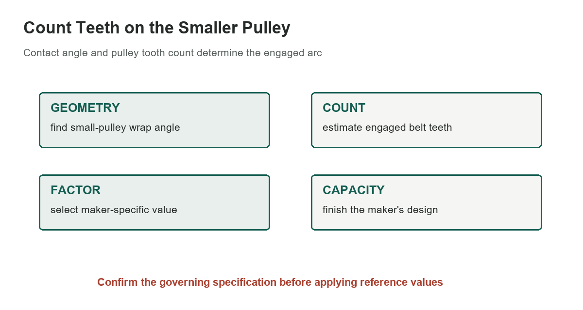
The teeth-in-mesh count depends on the small pulley’s tooth count and the belt’s contact angle. A common geometric estimate multiplies the pulley tooth count by the fraction of a full revolution covered by the wrap angle. Use the exact convention and rounding rule specified by the selected manufacturer’s manual.
The count is not necessarily an integer before rounding. The Mitsuboshi manual instructs users in its method to round the calculated tooth count down before selecting its factor. Other manufacturers can define the method, minimum contact, or rating basis differently.
Read the correction sequence
The historical table assigns 1.00 for six or more engaged teeth, then decreases the factor for five, four, three, and two teeth. The lower values adjust a belt rating in the associated design method; they do not state that an individual tooth carries a fixed percentage of load under every operating condition.
The visual source page is a plotted chart followed by Table 46. The extracted OCR file contains chart labels and scattered fragments, so it was not used for the factor values. The five entries in this article were checked directly against the rendered page and against the Mitsuboshi manual’s corresponding sequence.
Keep factors within one manufacturer method
Mitsuboshi’s design manual uses a teeth-in-mesh factor inside its belt-width calculation. That confirms the general role of such a correction but does not make its full calculation interchangeable with the historic table or a different belt maker’s method. Profiles, construction, ratings, service factors, and minimum pulley sizes vary.
Use the maker’s complete design procedure, including base power rating, belt width, length, speed, start-stop duty, temperature, and environmental allowances. Do not multiply a catalog rating by a factor from another supplier and assume the result is an approved design.
Check the whole drive layout
A low engaged-tooth count may prompt a layout review: small-pulley tooth count, center distance, wrap angle, belt length, alignment, tension, and peak torque all matter. A larger pulley or different center distance may increase contact, but any redesign must preserve package clearance, speed ratio, and the machine’s load requirements.
The site’s scooter drive-belt chart identifies a separate belt application and is not a synchronous-belt rating reference. The narrow V-belt cross-section guide addresses another belt family, and the V-belt speed-ratio guide covers a different correction table.
Inspect installation and operating conditions
Synchronous belts require compatible pulleys and proper alignment. Follow the manufacturer’s installation tension and handling instructions; do not lever a belt over a flange or tooth with power connected. Inspect pulley wear, tooth damage, contamination, and flange condition before reuse or replacement.
Guards should be installed before operation, and the drive isolated before inspection or adjustment. A teeth-in-mesh factor cannot correct misalignment, damaged teeth, contamination, incorrect tension, or an overloaded drive.
Document the design basis
Record the belt manufacturer and profile, pulley tooth counts, center distance, calculated wrap, engaged-tooth count, selected factor, rating basis, belt width, service factor, and the manual revision. This makes the decision reviewable if the drive is later changed or a belt fails prematurely.
Use this chart only as a quick lookup after identifying the correct method. For a safety-critical drive or one with high starting torque, obtain a manufacturer or qualified engineering review. The factor alone cannot predict belt life or verify the complete system.
Sources: Mitsuboshi timing-belt design manual, Gates synchronous belt design manual, Original handbook extraction