A linear actuator under compression can fail by buckling before its motor or screw reaches a nominal thrust limit. The relevant column length is not always the physical extension: support and joint restraints change the shape the member can take when it bends. The selected factors below translate four idealized end conditions into an equivalent length for an Euler-style column calculation. They are a mechanics reference, not an actuator capacity chart.
[gs_table id=”11322″]
Read the boundary condition, not just the factor
The 2L case represents a rigidly mounted actuator with a free load end; the L case represents pin-connected ends. The 0.7L and 0.5L cases represent progressively stronger idealized restraint. These labels describe the load path and rotational restraint at the ends, not merely whether a bracket looks substantial. Real clevises, spherical bearings, flexures, bolted mounts, and frames can have partial restraint.
Choose a factor only when the installed geometry genuinely matches its assumed support. If the attachment can rotate, translate, slip, or deform, a rigid-end idealization may overstate stability. The source’s words describe actuator/load fixations; translating them to a different machine requires a competent model of the actual assembly.
Understand the square-law effect
Euler’s ideal elastic buckling relation is commonly written as Pcr = pi squared times E times I divided by Le squared. Here E is elastic modulus, I is the relevant second moment of area, and Le is effective length. Because length is squared, doubling Le reduces the ideal critical load to one quarter when every other assumption remains unchanged. A modest error in restraint classification can therefore produce a large change in the theoretical result.
The equation assumes a straight, uniform, elastic member under concentric axial compression with idealized restraints. Initial curvature, eccentric force, thread-root dimensions, joints, clearance, local yielding, material variability, and lateral loading can all reduce real capacity. Do not treat a textbook Euler result as a certified working load.
Use the actuator manufacturer’s selection method
Manufacturers publish product-specific buckling limits because screw diameter, extension, support arrangement, and internal construction vary. Tsubaki’s selection guidance says compressive load must remain below the allowable buckling load and instructs users to consult its product graph and calculation method. Its worked example uses a stated safety factor and installation condition; those assumptions belong to that product family, not to every actuator.
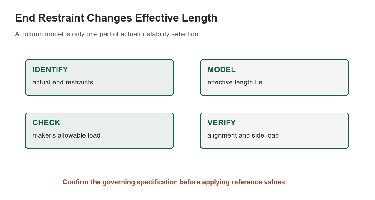
Check the exact actuator model, stroke, mounting orientation, duty, speed, load point, and any side or overhung forces. Include the structure that carries the actuator: a stiff actuator cannot compensate for a flexible bracket or frame. If linked actuators share a load, verify distribution and synchronization rather than dividing total load evenly by assumption.
Keep side loads and alignment in view
A simple Euler column equation describes axial instability, not every failure mode. Side force from a misaligned guide, a moving load that swings, or a bracket that twists can bend the screw and change the effective support. Tsubaki’s product selection example separately calls out preventing lateral loads and checking product limits, illustrating why the equivalent-length factor is only one input.
Use independent guides where the actuator manufacturer requires them, align attachment points through the full stroke, and prevent a load from imposing unintended transverse force on the screw. Inspect pins, clevises, welds, fasteners, and the supporting frame. A binding mechanism can create forces not represented in a static thrust calculation.
A practical selection sequence
Start with the maximum compressive force at the actuator, including load, acceleration, friction, and any application-specific service factors. Identify the true unsupported length and end restraint at the worst extension. Then use the manufacturer’s allowable-load data for that configuration, applying its prescribed safety margins and checking speed, life, thermal duty, and mounting limits.
The site’s garage-door opener guide covers a different powered mechanism, while the engine-hoist guide concerns lifting equipment; neither provides actuator buckling ratings. For machine support context, see the bench-vise guide. Consult a qualified engineer for a load-bearing or safety-critical installation.
Sources: Tsubaki Linipower Jack selection and buckling guidance, NISTIR 6779, Euler column buckling and effective length, Original handbook extraction