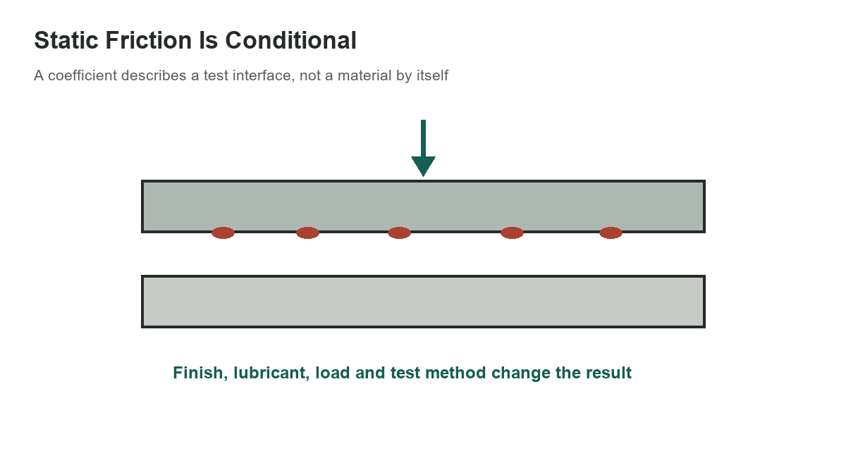
A static-friction coefficient is not a fixed property printed on a material label. It describes the resistance to the start of sliding for a particular contact pair and test condition. Surface finish, contamination, oxide, lubricant, contact pressure, alignment, dwell time and test method can all change the result.
Selected values are examples, not allowables
The values below are a small selection from a historical reference table. “Clean” and “lubricated” are the source’s categories; they do not specify a modern surface preparation or lubricant grade. Use the figures to understand the scale of reported values, not to approve a safety-critical joint.
[gs_table id=”11180″]
For a simple block-on-plane model, the limiting friction estimate is F = μN, where N is the normal force. Before sliding, static friction can take any value up to that limit; it is not automatically equal to μN. This elementary relation is useful for a first check, but real interfaces may not behave as a single, constant coefficient over every load and motion condition.
Why steel-on-steel values disagree
Different tests can produce widely different steel-on-steel coefficients. ASME summarizes static values reported in references ranging from about 0.15 to 0.78 and notes that even nominally similar specimens have shown substantial spread between laboratories. A separate experiment found that dynamic loading and sliding history changed measured static friction for steel-on-steel contacts. These findings are a warning against choosing a favorable number from a generic chart.
“Clean” is especially ambiguous. It may mean degreased, freshly machined, oxidized, polished or simply free of visible dirt. A small oil film can reduce friction, while wear, corrosion, vibration or surface damage can shift it again. A bolt-preload calculation, brake interface, clamp, sliding support and shop fixture each have different contact geometry and acceptance requirements.
When a reference value can help
A reference coefficient may help estimate a range for a noncritical concept check, compare the likely influence of lubrication, or identify whether friction deserves further investigation. Keep the source, test conditions and uncertainty beside the result. Do not turn a single tabulated coefficient into a guaranteed minimum or maximum without an applicable specification.
For a critical design, use a governing standard or a qualified test program that represents the actual materials, finish, lubricant, pressure, temperature, speed, dwell and environment. Where slip is not acceptable, use positive mechanical restraint, a qualified bolted-joint method or another engineered load path rather than relying on an optimistic generic coefficient. Consider the consequence of both higher and lower friction where the system must move predictably.
Document the interface, not just μ
A usable test record identifies both materials and their grade, the surface preparation, coating or oxide condition, lubricant and amount, normal load, contact geometry, temperature, dwell time, motion rate and measurement method. Record whether the number is static breakaway friction or steady sliding friction. These are different quantities and should not be swapped in a calculation.
For related shop inspection decisions, see the Rockwell hardness scale guide. Hardness can describe resistance to indentation, but it does not supply a universal friction coefficient for the same material. Friction is also discussed in the friction-wheel horsepower examples, where rolling contact and drive power are treated as a separate engineering problem. For fastener identification, see the bolt and wrench size chart.
Practical takeaway
Use the selected examples as historical context only. The values are not a ranking of steel, brass and cast iron, and the clean/lubricated labels are not test specifications. If friction controls safety, holding capacity or reliable motion, characterize the actual interface or follow the applicable design standard.
Selected coefficients: Machinery’s Handbook, 31st edition, Table 1, printed page 173, which attributes the table to Bowden and Tabor’s The Friction and Lubrication of Solids, Volume 1. For general context, see the ASME discussion of friction.