The historic friction-wheel table is a horsepower reference, not a rotational-speed chart. It estimates transmitted power from wheel diameter, rotational speed, face width, normal force per unit width, and a friction coefficient. The examples below recalculate a few cases using one stated assumption set; they are not ratings for a modern wheel, coating, shaft, bearing, frame, or drive.
Use the model with its assumptions
For diameter D in inches, speed N in revolutions per minute, face width W in inches, contact force P in pounds per inch of face, and coefficient f, the handbook model is HP = 3.1416 × D × N × P × W × f ÷ (33,000 × 12). For the examples, P is 150 lbf/in and f is 0.20. This reduces the coefficient to about 0.000238 horsepower per (inch × rpm × inch of face).
The values shown use W = 1 inch and round the calculated result to three decimal places. For a different face width or load per inch, the result changes linearly in this simplified equation. The table is only a calculation example and must not be read as a permitted operating limit.
[gs_table id=”11051″]
Understand what the result leaves out
The equation treats friction as a single coefficient and assumes the stated normal force is distributed across the face. Actual traction depends on contact pressure, surface material, finish, temperature, contamination, wear, alignment, elastic deformation, and whether the drive starts under load. Coefficient values are not universal constants for a material pair; operating conditions can change them substantially.
Slip converts mechanical energy into heat and wear. A large calculated horsepower does not establish that the wheel can dissipate heat, that the contact patch remains stable, or that a shaft and bearing can carry the load. The formula also omits acceleration, torque ripple, service factor, shock, losses elsewhere in the drivetrain, and material fatigue.
Check the actual machine
Use current data from the friction-wheel manufacturer for the exact compound, hardness, diameter, face width, normal load, speed, duty cycle, and ambient conditions. Verify the shaft, hub, bearings, frame, guarding, and braking arrangements as a system. If a manufacturer does not publish the required rating or test basis, do not substitute this old example for engineering approval.
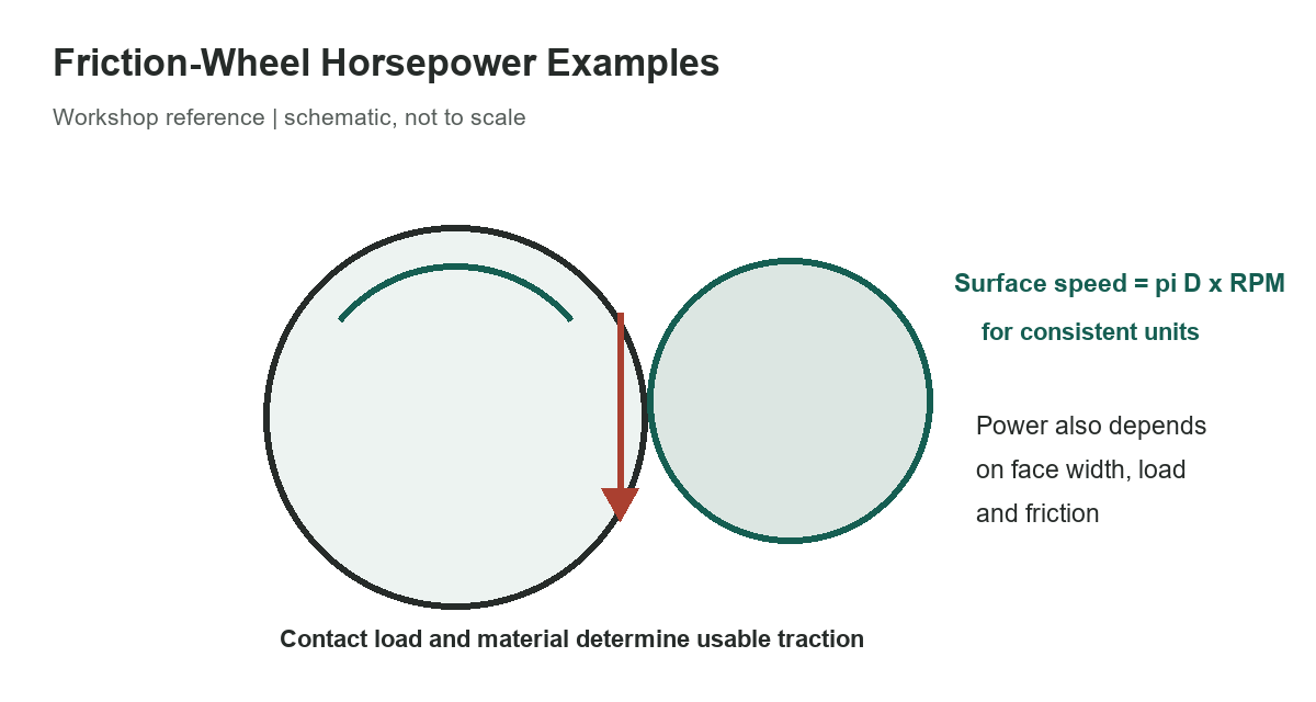
Speed can be checked separately from power. The wheel’s surface travel per minute is circumference multiplied by rpm, with consistent units. That result helps describe contact speed, but it does not give the friction force or transmitted horsepower on its own. Power requires both a force component and motion, and friction-drive losses and slip must be considered.
Do not increase pressure to chase a number
More normal force can increase available traction in a simplified Coulomb-friction model, but it also raises contact stress and bearing load. Excess pressure may deform or damage a compliant wheel, shorten its life, or overload the support structure. Follow the current product instructions and machine limits instead of adjusting spring force until the calculated horsepower is reached.
Keep hands, clothing and loose material away from the nip point. OSHA’s construction-industry machine-guarding rule addresses exposed friction-drive contact points; the specific requirements that apply depend on the workplace and machine. Never remove a guard to inspect a running drive. Stop, isolate and secure the machine according to its lockout procedure before inspection or adjustment.
Record the measured wheel diameter, speed under load, face width, material identification, contact force and operating conditions whenever an engineering calculation is made. A traceable calculation can then be reviewed against current manufacturer data and the applicable safety requirements.
Related references: grinding-wheel speed calculations, narrow V-belt sheave dimensions, and variable-speed V-belt lengths.
Formula and scope
The examples use the handbook’s friction-wheel horsepower equation and a selected set of its stated assumptions. Values were recalculated from the full coefficient rather than copying the full historical lookup matrix. The equation is a screening calculation only; use current product ratings and machine-specific engineering review. OSHA’s cited rule is specific to construction workplaces. Machinery’s Handbook, 31st edition; OSHA 29 CFR 1926.307(g).