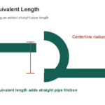
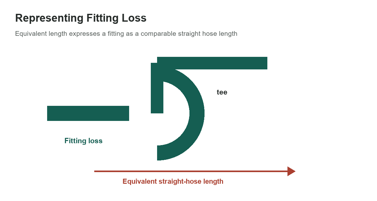
A pneumatic fitting creates resistance to airflow. The equivalent-length method represents that resistance as a comparable length of straight hose, allowing a designer to combine straight runs and fitting contributions within a compatible pressure-loss method. The values below are selected examples from a Parker pneumatic connector catalog, not universal values for every elbow, tee or tube system.
[gs_table id=”11234″]
Check what the length refers to
The Parker table expresses fitting resistance as equivalent length in metres of hose and groups the values by fitting bore. That is a manufacturer-specific comparison for the catalog’s fitting system. It is not the nominal pipe size, the fitting’s physical length or a value that can be transferred to a different bore without checking the manufacturer’s data.
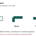
At the same bore, a tee with flow turning through the branch has a different equivalent length from a tee with flow passing in line. The flow path is part of the lookup. Select the row that matches how the air actually passes through the fitting, and include each fitting on the relevant branch of the network.
How equivalent length is used
In an equivalent-length calculation, the fitting length is combined with straight hose or pipe length and evaluated using a matching friction or pressure-drop method. The method’s basis must match the fluid, bore, material, flow range and reference conditions. Do not combine an equivalent length with a separate local-loss coefficient for the same fitting unless the calculation explicitly accounts for both without double-counting.
Compressed air is compressible, and pressure drop depends on upstream pressure, flow, temperature, line bore, hose construction and the components in series. A simple incompressible liquid equation may not be adequate. Parker’s pneumatic technical guidance describes pressure drop and flow factors such as Kv; use the equation and reference conditions required for the selected pneumatic components.
Do not substitute the liquid fitting chart
The older handbook page places liquid-fitting and pneumatic-fitting tables in the same chapter, but they describe different systems. Liquid equivalent-length examples should not be used as compressed-air settings. The pipe-bend equivalent-length guide addresses liquid pipe-flow ratios and geometry. For compressed-air line sizing and pressure-loss context, see the compressed-air pipe size and flow reference.
For a separate geometry-change case, the pipe expansion and contraction guide explains local losses caused by changing flow area; it does not replace pneumatic connector data.
A fitting’s flow coefficient, equivalent length and maximum working pressure answer different questions. Pressure rating is not a measure of flow capacity. Confirm connector material, seal compatibility, working pressure, temperature and installation method from the exact current product documentation.
Build a system-specific estimate
List the tube or hose internal diameter, total straight length, fitting model and flow path, operating pressure, expected flow and required downstream pressure. Use one consistent manufacturer or engineering method to account for tubing and components. If the route includes branches, valves, filters, regulators or quick couplers, include their resistance rather than treating the elbows as the only losses.
After estimating, measure pressure at the point of use under the real operating flow. Static pressure with no air demand can conceal a restriction. If a tool slows or a cylinder cycles inconsistently, check the regulator, filter, hose bore, couplings and supply conditions before replacing fittings based only on nominal size.
Use catalog values with their stated limits
The values shown are a compact reference for three bore sizes and common flow paths. They do not establish a universal minimum pressure, compressor size or safe operating pressure. Use the current catalog for the exact fitting family and ask the manufacturer for application support when flow is high or pressure margin is small.
Sources: Parker Pneumatic Connectors Design Manual and Parker Pneumatic Technical Guidelines.