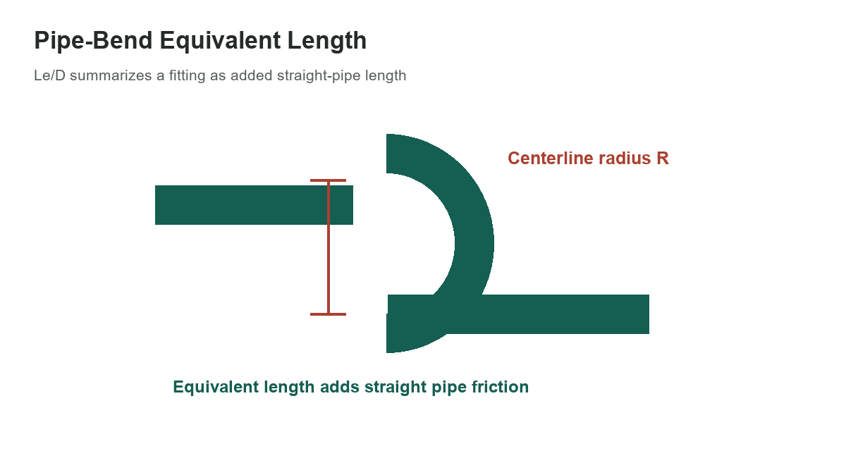
Equivalent length represents a fitting’s pressure loss as an added length of straight pipe. The selected ratios below cover a few radius bends and miter bends; they are not a complete fitting catalog. Match the bend geometry and diameter convention before using a value.
Selected bend ratios
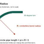
R is the bend centerline radius and D is the pipe diameter specified by the source. Le/D is dimensionless. The source’s radius-bend entries apply to a 90-degree bend; its miter-bend entries are grouped by turn angle. Do not fill the “not specified” radius cells with an assumed value.
[gs_table id=”11188″]
For a source entry with Le/D = 12 and a matching pipe diameter D = 2 inches, the equivalent straight length is Le = 12 × 2 = 24 inches. That length is added to straight-pipe length only when using the same friction-factor basis and method assumed by the source. Changing the diameter units changes the calculated Le units, not the dimensionless ratio.
Equivalent length and K are related methods
A fitting loss can also be represented by a loss coefficient K in a velocity-head equation. The methods are not interchangeable without a compatible friction factor, reference diameter and flow basis. ASHRAE explains that the equivalent-length method converts local losses into a length of uniform conduit, while K applies a coefficient to a velocity term. Use one method consistently and do not add both representations for the same fitting.
Equivalent length depends on the reference pipe friction factor. ASHRAE notes that errors can occur when the conduit roughness differs from the reference used to establish the equivalent length. Coefficients and equivalent lengths also depend on geometry and, in some cases, Reynolds number. Nearby bends can interact before the disturbed flow profile recovers, so adding isolated fitting values can overstate or understate system loss.
Pipe bends are not duct elbows
Do not apply a circular-pipe bend ratio to a rectangular air duct. Duct losses depend on cross-section, aspect ratio, turning vanes, area changes and fitting construction. ASHRAE treats duct fittings separately and explicitly distinguishes the behavior of pipe fittings from duct elbows. Select data for the actual system and fluid.
These ratios also do not specify a pressure rating, material, wall thickness, corrosion allowance or allowable operating temperature. A fitting may be dimensionally similar but have a different internal contour or area. For pressure piping, select the fitting and design method required by the governing code and the project’s adopted edition.
Use a consistent calculation
List the straight-pipe length, internal diameter, fluid, flow rate, bend geometry and friction-factor method. Convert each matching Le/D entry using that pipe diameter, add the equivalent lengths to the straight run, then calculate friction loss using the chosen pipe-flow method. If using K instead, sum applicable fitting coefficients with the distributed pipe-friction term. Keep the source and method attached to every value.
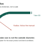
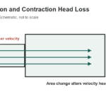
For identification, see the pipe fitting types guide. For a different flow problem, the pipe expansion and contraction guide covers area-change losses rather than bend equivalent lengths. The PE pipe bend-radius guide covers tubing installation geometry, not hydraulic equivalent length. Air systems require duct-specific information; do not transfer these pipe numbers to a duct layout.
Check the design before relying on a chart
Use the table for a preliminary comparison only when its fitting type and method match the system. For final design, use a current engineering reference or fitting manufacturer’s data for the actual geometry. If a result is sensitive to friction loss, use the adopted method, verify assumptions and account for interactions between closely spaced fittings. Record the diameter basis and reference edition with the calculation.
Table values: Machinery’s Handbook, 31st edition, Table 24, “Bend Equivalent Length Ratio,” printed page 2783. For equivalent-length method context and limitations, see the ASHRAE Handbook—Fundamentals, Chapter 3: Fluid Flow.