Galvanic corrosion can occur when dissimilar electrically conductive materials are connected while exposed to a shared electrolyte, such as water containing dissolved salts. The more active material can corrode preferentially. A metal pair that performs acceptably indoors may behave differently in a wet, salty, polluted, or continuously immersed environment, so a universal green/red compatibility chart can give false confidence.
Screen the whole joint
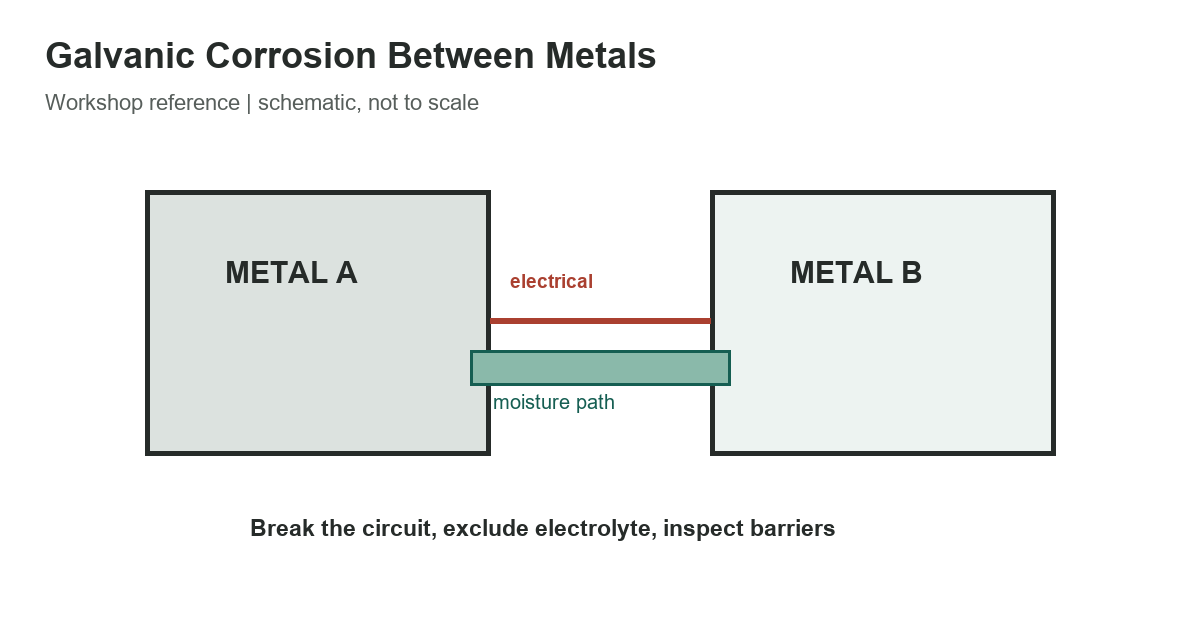
Two conditions are central: an electrical path between the metals and an electrolyte that can carry ionic current. If either is reliably removed, the galvanic circuit is interrupted. The table turns those conditions into a practical screening checklist. It is not an alloy-pair approval and does not assign universal corrosion ratings.
| Electrical contact | Completes the dissimilar-metal circuit | Use a compatible nonconductive barrier where suitable |
|---|---|---|
| Conductive moisture | Electrolyte enables ionic current | Exclude water; seal and drain the joint |
| Salt or contaminants | Can raise electrolyte conductivity | Consider the real exposure and washdown |
| Area imbalance | Small anodic area beside large cathode can corrode rapidly | Avoid unfavorable geometry; coat and isolate both sides |
| Damaged coating or isolator | Creates a local path at a vulnerable spot | Inspect edges, fasteners and barrier condition |
5 rows
Scroll horizontally to view all columns.
NASA’s corrosion-control guidance also emphasizes geometry and area. A relatively small anodic component coupled to a much larger cathodic surface can experience concentrated attack. Coating only the anodic part can be risky if a small defect exposes it while the larger cathode remains active; coating both surfaces and treating edges and fasteners consistently can reduce that concern.
Environment changes the ranking and rate
Electrolyte conductivity, temperature, oxygen availability, wet/dry cycling, flow, deposits, and crevices all influence corrosion. Salt contamination can make a thin film more conductive. A marine immersion result does not automatically predict the behavior of an intermittently damp indoor bracket, and a dry indoor compatibility list does not establish suitability for road salt or outdoor exposure.
Alloy family alone may not be enough. Different grades, heat treatments, surface finishes, welds, passivation states, and coatings can change behavior. Aluminum alloys, stainless grades, plated steels, and copper alloys should be identified precisely. If a joint is important, use data for the actual alloys and service environment, not only a broad metal name.
Use isolation and coatings thoughtfully
Electrical isolation can be provided by suitable sleeves, washers, gaskets, or bushings, provided they maintain the required mechanical load, temperature, chemical, electrical, and fire performance. The fastener itself can bridge a barrier, so inspect the complete path through bolts, threads, washers, and mounting surfaces. Sealants and coatings must also be compatible with the materials and service.
Protective coatings work best when they remain continuous and their edges are managed. A scratched coating, cut edge, poorly sealed lap, or trapped moisture pocket may create a small active area. Design for drainage and inspection where possible, avoid crevices that retain electrolyte, and follow the coating maker’s preparation and repair instructions.
During inspection, look beyond visible rust or discoloration. Check under washers, around cut edges, at coating breaks, and where water can collect between overlapping parts. White deposits, blistering, staining, or a loose isolating washer can signal that the barrier is no longer doing its job. Clean and repair the joint using a procedure compatible with the alloy and coating; simply painting over active corrosion may trap moisture and hide continued damage.
When to require an engineering review
For safety-critical structures, pressure equipment, electrical enclosures, vehicles exposed to road salts, and immersed components, use a qualified corrosion engineer or the responsible design authority. Confirm electrical bonding requirements before adding isolators; a barrier that interrupts a corrosion circuit may also compromise protective grounding. Corrosion control must not defeat electrical safety, lightning protection, structural capacity, or code requirements.
- Identify both alloys, finishes, coatings, and fasteners.
- Describe the actual moisture, salt, temperature, and wet/dry exposure.
- Check electrical continuity through every bolt and interface.
- Review cathode/anode area balance, crevices, drainage, and coating edges.
- Verify grounding and structural requirements before isolating a joint.
Read the reference chart library, compare running-board construction materials, and use the PVC pipe reference for a separate material-identification example.
References
NASA’s galvanic corrosion-control standard discusses electrical isolation, coatings, and area effects. The U.S. Navy corrosion manual describes marine environmental factors; use its context-specific guidance accordingly.