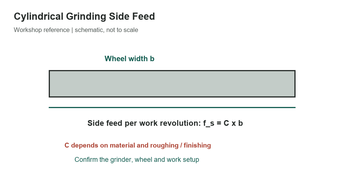
In traverse cylindrical grinding, side feed describes the table movement across the wheel face for each work revolution. A handbook relationship expresses it as the side-feed factor C multiplied by wheel width b. The factor varies with work material and whether the operation is roughing or finishing. These calculations illustrate the relationship; they are not a recommended setting for every grinder. For related shop references, see our grinding-wheel speed guide, grinding-wheel selection guide, and bench-vise guide.
Calculated side-feed examples
The table holds wheel width at 0.25 inch and multiplies it by selected roughing or finishing factors. Values are rounded to three decimal places. The unhardened-steel source gives ranges, so both ends are shown as calculations; single-factor rows show the result for that factor only.
[gs_table id=”10912″]
For the first example, 0.25 × 2/3 equals 0.1667 inch per work revolution, displayed as 0.167 inch. At the upper roughing factor of 3/4, the result is 0.1875 inch, displayed as 0.188 inch. These values describe a mathematical relationship, not a guarantee of finish, wheel life or safe machine performance.
Apply the relationship carefully
Use the wheel width that is actually available for the grinding pass, not a nominal wheel dimension that includes a relieved or unusable section. Confirm whether the machine’s feed scale is expressed per work revolution, per minute, or in another unit. Confusing traverse feed with wheel infeed or work rotation can produce a large process error.
The source groups factors by material and roughing or finishing operation. Workpiece hardness, geometry, wheel specification, dressing condition, machine rigidity, coolant delivery, speed and stock allowance all influence a stable setup. Treat the tabulated factor as a reference for understanding the method, not as a substitute for the machine builder’s operating guidance or the abrasive maker’s application data.
Side feed is one part of a cylindrical grinding cycle. The operator must coordinate traverse feed with depth of cut, work speed, wheel speed, spark-out, dressing and the required surface finish and tolerance. A high feed can increase productivity but can also raise force, affect the finish or cause thermal damage. A conservative result in a formula does not assure that the complete machine setup is suitable.
Choose roughing and finishing separately
Roughing removes more stock and commonly uses a larger traverse increment than finishing in the cited reference. Finishing aims to achieve final size and surface condition with a smaller feed. Do not use a finish value simply because the part is near size; first verify the remaining allowance, wheel condition and machine response.
Make a controlled trial on representative material. Record the wheel specification and width, dressing method, work speed, wheel speed, coolant, side feed, infeed, spark-out, measured size and surface result. Change one setting at a time when possible, and follow the manufacturer’s maximum operating speed and guarding instructions. Stop if the wheel is damaged, vibration increases, coolant delivery fails or the work shows burn or cracking.
For a different wheel width, recalculate using f_s = C × b, keeping the same units for b and the resulting traverse increment. For example, doubling b doubles the calculated feed when C remains fixed. That arithmetic does not prove that the larger feed is appropriate; the machine, part, wheel and quality requirements must still support it.
When this chart is not enough
The relationship applies to the cited cylindrical traverse-grinding context. It should not be transferred automatically to plunge grinding, centerless grinding, surface grinding or a CNC cycle using a different feed convention. Those processes have different kinematics and controls. Consult the machine and wheel documentation for the correct parameter definitions.
If the work is safety-critical, heat-treated or crack-sensitive, establish process limits with a qualified grinding specialist and the responsible engineer. Inspect the finished part using the specified methods. This chart supplies example arithmetic only; it is not a process qualification or acceptance standard.
Sources
The selected factors and relationship were transcribed from the reviewed handbook passage. The Open University explains cross-feed’s relationship to wheel width in its grinding overview; Norton discusses how process parameters affect finish and thermal damage in its grinding considerations. Follow the exact grinder and wheel instructions for production work.