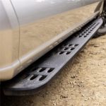
When power running boards stop deploying or retracting, start with the symptom and identify whether the system is factory-installed or aftermarket. Common failure categories include mechanical binding, ice or debris, lost power, a blown fuse, door-status input problems, damaged wiring, controller faults, and failed motors or linkages. Use the exact vehicle and product manual for fuse locations, connector tests, calibration, and replacement procedures.
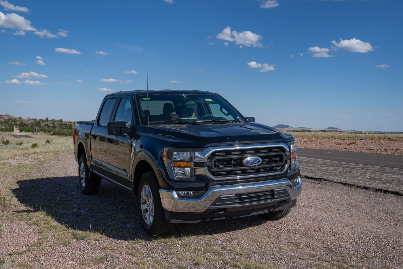
Ford F-150 photo by Tony Webster, Wikimedia Commons, CC BY 2.0; resized and recompressed for GarageSanctum as a general powered-step vehicle reference.
60-second diagnostic flow
Use the first branch that matches the symptom. The links jump to safe inspection stages; they do not replace the product manual.
- Is the system factory or aftermarket? Identify the vehicle, board brand, model, and installation manual. Continue to identify the system.
- Do neither side work? Start with power, fuse, and controller checks.
- Does one side work? Start with the one-side branch and inspect that side’s hinge, linkage, connector, and motor.
- Does the motor run but the board stay still? Go to motor-no-movement checks.
- Does the board stop halfway or repeat its cycle? Inspect binding, ice, debris, and obstruction protection.
- Does it fail only in cold or wet weather? Start with weather-related checks, then use the exact manual for moisture and connector inspection.
- Are the lights on but the board does not move? Treat lighting and board movement as separate circuits until the manufacturer says otherwise; continue to input and controller checks.
Symptom to first safe check
| Symptom | Likely failure category | First safe check | Do not assume |
|---|---|---|---|
| Neither board moves | Battery feed, fuse, ground, controller, door input, or shared harness | Confirm the system model and inspect the manual’s power and fuse path | A larger fuse is a fix |
| One side moves | Side-specific motor, linkage, connector, or mechanical binding | Compare the stationary side with the working side without placing hands in the mechanism | The controller is automatically bad |
| Board stops halfway | Ice, grit, bent linkage, obstruction detection, low voltage, or worn pivot | Inspect for visible obstruction with the system secured | More force or a bypass is safe |
| Motor runs but board does not move | Stripped gear, disconnected linkage, failed pivot, or broken drive arm | Stop cycling and inspect only as the manual permits | The motor needs more voltage |
| Repeated deploy/retract cycle | Door input, position feedback, obstruction detection, controller, or unstable power | Record exactly when the cycle repeats and check the manual’s diagnostics | A random reset clears the cause |
| Works after cleaning | Contaminated pivot, ice, water, or damaged seal | Identify why contamination reached the mechanism and inspect for wear | Lubricant alone repairs damage |
| Lights work, board does not | Separate motor, controller, input, or mechanical fault | Use the model-specific wiring and diagnostic procedure | The board has full power |
| Fuse opens again | Short, seized motor, damaged harness, or controller fault | Stop replacing fuses and isolate the system using the manual | A higher-rated fuse is acceptable |
Identify the system
Factory-installed boards
Factory systems can depend on the vehicle body controller, door-ajar status, network messages, current sensing, and vehicle-specific diagnostics. A generic aftermarket fuse number or connector diagram may be wrong. Use the owner’s manual, official service information, or the manufacturer support path for the exact vehicle.
Aftermarket boards
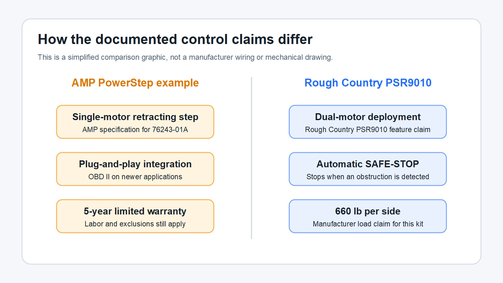
Record the brand, product family, part number, controller label, and installation date. Look for the installation manual and wiring diagram before touching a connector. A board that looks like an AMP, Rough Country, Westin, or ARIES product may use different motor connectors, controller logic, door inputs, and reset procedures.
If the board was recently installed, inspect the harness routing and ground point against the exact manual. Do not infer that a loose wire is safe to reconnect while the battery is connected. Follow the manual’s isolation and test sequence.
Mechanical inspection: binding, ice, and debris
Park on a stable, level surface and keep the door area clear. If the manual allows manual movement, use that procedure. If it does not, do not force the board by hand. Look from the side for packed mud, gravel, ice, bent brackets, a displaced mud flap, a traction bar, rocker damage, exhaust heat damage, or contact with a jack point.
Compare the deployed and retracted positions on both sides. A board that sits at a different angle, scrapes the rocker, or moves more slowly can point to a pivot or linkage issue. Keep clear of pinch points. Take photographs of the condition before cleaning so a technician can see what changed.
Use only the cleaner and lubricant named by the product manual. Do not spray a general penetrant into an electrical connector or motor housing. If cleaning restores movement only briefly, find the source of water, salt, grit, or corrosion and inspect the pivot, seals, motor arm, and fasteners.
Binding and obstruction protection
Obstruction protection can stop or reverse the board when it detects abnormal resistance. That protection is not a nuisance to defeat. Remove the visible obstruction, confirm that the board has a clear travel path, and retest only as the manual permits. Never hold the board open, bypass the current sensor, short an input, or alter a stop to make it complete a cycle.
Power and fuse checks
Power, fuse, and controller checks
If neither side moves, start with the system’s documented power path. Confirm the battery condition and the manual’s required ignition, door, or module state. Inspect the correct fuse and relay location listed for that system. A fuse that opens again indicates a fault; do not install a larger fuse or bridge the holder.
Use a meter only when the manual provides a safe test point, expected condition, and connector procedure. Keep probes away from adjacent terminals. Do not pierce insulation unless the service information directs it. A voltage reading with no load does not prove that a corroded connector can carry motor current.
Inspect the main ground, battery feed, controller connectors, and harness routing for corrosion, pulled pins, crushed insulation, heat damage, or water entry. Disconnect the battery or controller only as directed. Some systems can store diagnostic codes or require a specific power-down sequence.
Door input and position diagnosis
Input and controller checks
A board may depend on door-ajar status, a remote signal, a vehicle network message, a controller input, or a position sensor. If the interior or exterior lights also show an incorrect door state, resolve that vehicle-side issue through the official service path before replacing the board motor.
Record the exact trigger: driver door, passenger door, rear door, tailgate, ignition state, or manual switch. A system that responds to one door but not another points toward an input or wiring difference rather than a shared motor failure. Do not connect the input directly to battery power to test it. That can damage a body controller or violate the system’s safety design.
Motor runs but the board does not move
Motor-no-movement checks
Stop repeated cycling. A running motor with no board movement can indicate a stripped gear, disconnected drive arm, broken linkage, failed pivot, or a motor shaft that is turning without transmitting torque. Continuing to run the motor can turn a repairable linkage problem into a controller or motor failure.
With the system secured and the manual’s procedure in hand, inspect the drive arm, pivot fasteners, linkage pins, and board bracket. Look for a missing retaining clip, elongated hole, bent arm, broken gear housing, or a board that has separated from its mount. Do not weld, drill, or substitute a fastener until the manufacturer identifies the repair part and specification.
One side only
One-side diagnosis
When one board works and the other does not, compare the stationary side’s visible condition with the working side. Check the side-specific connector, harness branch, motor, arm, pivot, and fasteners. A single dead side makes a shared battery fuse less likely, but it does not prove that the motor is bad.
If the controller provides separate diagnostics, use the manufacturer’s procedure. Do not swap motors or connectors as a first test unless the manual approves that method. An unapproved swap can move a fault into a working circuit or damage a controller.
Cold, wet, or intermittent failure
Weather-related and intermittent checks
Cold-weather failures often involve ice, thickened contamination, low battery voltage, or a pivot that is already worn. Wet-weather failures can involve water in a connector, damaged seals, corrosion, or a harness that has been routed into a splash zone. Record the outside temperature, moisture, which door triggered the board, and whether the failure occurs on deployment, retraction, or both.
Dry and clear the mechanism only as the manual permits. Do not heat a motor or connector with an open flame. Do not force an iced board with a lever. If the board works after warming but fails again, diagnose the underlying clearance, seal, corrosion, or voltage problem.
Relearn and calibration
Some systems support a manufacturer-documented relearn or calibration procedure. Use it only when the exact manual identifies the model and the conditions. Calibration is not a substitute for a blocked pivot, failed motor, damaged input, or low voltage.
Do not use forum reset tricks that require holding a switch, bypassing a sensor, disconnecting a vehicle module, or cycling the board repeatedly unless the manufacturer documents that procedure. A reset can hide a fault while leaving the mechanism unsafe.
When to stop and use a technician
Stop work and use a qualified technician when the board moves unexpectedly, the vehicle wiring or body controller is involved, the fuse opens again, a motor or linkage has failed, the truck has collision or rocker damage, the system is under warranty, or the manual does not define the next test. Also stop if the board is supporting weight, the vehicle is not safely parked, or you cannot keep clear of the pinch points.
Ask the technician to record the symptom, fault codes, voltage under load, connector condition, mechanical damage, and replaced part. That record helps distinguish a recurring power problem from a motor failure.
For buying and fitment, see the best power running boards guide, the F-150 power running-board guide, and the Silverado/Sierra fitment guide.
Sources and method notes
Use the current product and vehicle documentation from AMP Research, Rough Country retractable steps, Ford Support, Chevrolet Support, and GMC Support. This guide intentionally avoids generic fuse numbers, wire colours, undocumented reset tricks, and bypass instructions because those details vary by vehicle and product revision.