ASME B18.2.1-2012 Table 5 gives bolt-length tolerances by nominal length and nominal size. The table below reproduces the listed plus and minus deviations in inches; “Not listed” marks size-and-length cells left blank in the standard.
[gs_table id=”11205″]
Understand the measurement
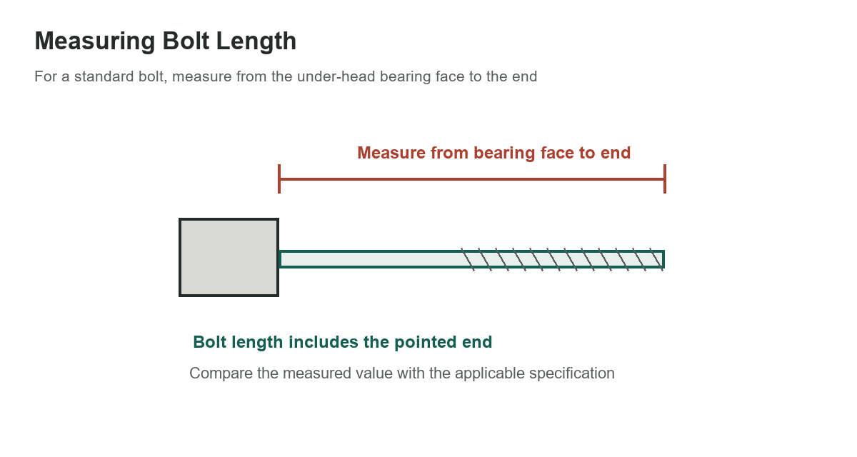
For a conventional hex-head bolt, length is generally measured from the bearing face under the head to the extreme end, including the point. The illustration shows that measurement direction. Countersunk fasteners and other head forms may use a different reference surface. Confirm the measurement definition in the applicable drawing or standard before comparing a measured part with a nominal length.
Each cell shows the upper deviation first and lower deviation second. For example, +0.04 / -0.06 means the standard’s tolerance extends 0.04 in. above and 0.06 in. below nominal for that category. These are dimensional tolerances, not strength ratings or thread-length requirements.
Keep the sign attached to the value when recording an inspection result. A negative deviation describes a measurement below nominal; it is not a symmetric plus-or-minus tolerance. Do not silently convert it into a range centered on nominal, and do not assume the same limit applies to a longer bolt, a different diameter group or another head style. If the source note is incomplete for the part under inspection, locate the controlling specification before making a disposition.
Identify the standard and bolt type first
ASME B18.2.1 covers dimensional requirements for specified inch-series square and hex head bolts and related products within its scope. Structural heavy hex bolts are addressed under a separate standard. Other products, including metric fasteners, specialty bolts and proprietary parts, may follow different requirements. Even a familiar head shape does not establish which standard controls.
Check the purchase specification, drawing, grade, head style and standard edition. A procurement note may specify a different tolerance or inspection rule. Use the edition adopted by the contract or governing code, not an older chart merely because it is convenient. The bolt and wrench size chart helps identify common head and tool dimensions but does not define length acceptance. The American wrench size chart covers wrench openings, not bolt length limits.
Apply the values carefully
First determine whether the nominal length falls in the correct row and the nominal diameter in the correct column. Then measure from the prescribed datum with a method suitable for the head form. Account for measurement uncertainty and any inspection sampling rules specified by the applicable standard or quality plan. Do not round a borderline measurement into compliance.
The historical excerpt uses a small number of diameter groups and two length bands. It does not include every size, head style or tolerance condition. The complete governing standard may define exclusions, special cases, measurement details and product types that change the interpretation. Never use these values alone to accept a load-bearing assembly.
When the fastener is safety-critical
For structural, pressure, lifting or other safety-critical joints, use the specified fastener standard and engineering acceptance criteria. Dimensional compliance does not establish material grade, traceability, coating, thread engagement, preload or suitability for a load. If the fastener identification is uncertain, quarantine it for verification rather than inferring its class from appearance.
For general size identification, see the bolt head and wrench reference. When working with a lag screw, use the relevant product-specific drawing and installation specification; do not transfer bolt tolerances to a different fastener family. NIST’s Fastener Quality Act resource provides context for fastener identification and quality requirements.
Sources: ASME B18.2.1-2012, Table 5 and NIST Fastener Quality Act resource.