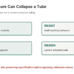
A pressure table can resemble a ready-made tube rating even when its material, geometry, and design assumptions do not match the part in front of you. The Machinery’s Handbook labels this lookup for tubes subjected to external pressure: it relates outside diameter and external working pressure to wall thickness and states a safety factor of 5. These selected historical values are not an internal-pressure rating and must not be used to rate a modern tube or pressure system.
[gs_table id=”11434″]
Read this as an external-pressure reference
The selected rows show the wall thicknesses listed for outside diameters of 8, 12, and 18 in. at the source’s external working pressures. The handbook states a safety factor of 5 and limits the underlying method to outside diameters from 7 to 18 in. and temperatures below 650 F. Those historical assumptions do not identify a universally applicable material, allowable stress, manufacturing tolerance, weld quality, corrosion allowance, or current code basis.
The same page also includes a smaller-diameter external-pressure lookup that gives maximum pressure for selected wall thicknesses. The site’s companion chart shows that alternate lookup format; both references concern external pressure, not separate internal- and external-pressure cases. External pressure can cause shell instability or collapse, so it requires a different design assessment from internal pressure.
Use the selected rows only to read the chart
For the 8-inch example, the selected wall rises from 0.174 in at 100 psi to 0.229 in at 220 psi. The 12- and 18-inch examples also show thicker listed walls as the selected pressure rises. These are copied historical entries, not a design formula or a modern material specification. The three rows are selected examples, not the complete chart, and no missing values have been interpolated.
The source prints two rows labeled 16 in. with different wall values. The page does not explain the distinction in the table heading, so confirm which entry applies in the full original context before using either one.
Do not turn a lookup into a working limit
Actual pressure-boundary design depends on the specified material and condition, outside diameter, minimum measured wall, manufacturing process, temperature, fluid, corrosion or erosion allowance, joints, supports, loads, inspection, and jurisdiction. A pressure label may refer to design pressure, working pressure, test pressure, or a component maximum; those terms are not interchangeable. The historical table does not provide enough information to establish any of them for a present-day tube.
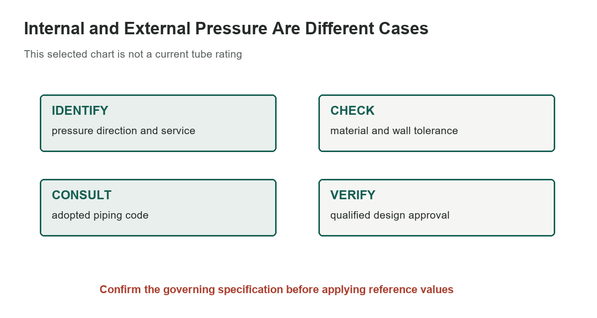
ASME B31.3-2024 covers process-piping materials, components, pressure design, fabrication, inspection, and testing within its scope. It is not a universal code for every garage, vehicle, or equipment assembly. Determine which code and edition the jurisdiction and system require, and have pressure-boundary decisions reviewed by a qualified engineer.
Compare tube references by product and purpose
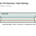
The site’s Parker Phastite tube ratings are manufacturer-specific assembly data for named tubing and connector conditions. The copper tube dimension reference describes selected sizes, not pressure capacity. A material or dimensional match to either page does not validate the handbook formula for a different application.
Stop before sizing pressure equipment
Do not use the historical values to select a tube, determine a safe operating pressure, set a relief device, or plan a pressure test. Use traceable manufacturer ratings and the governing code for the exact material, geometry, temperature, fluid, joints, and service conditions. If any required property or design input is unknown, obtain qualified engineering review before the system is pressurized.
Sources: Machinery’s Handbook, 31st edition, external-pressure tube table, printed page 294, ASME B31.3-2024: Process Piping