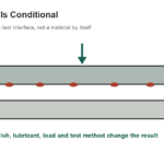
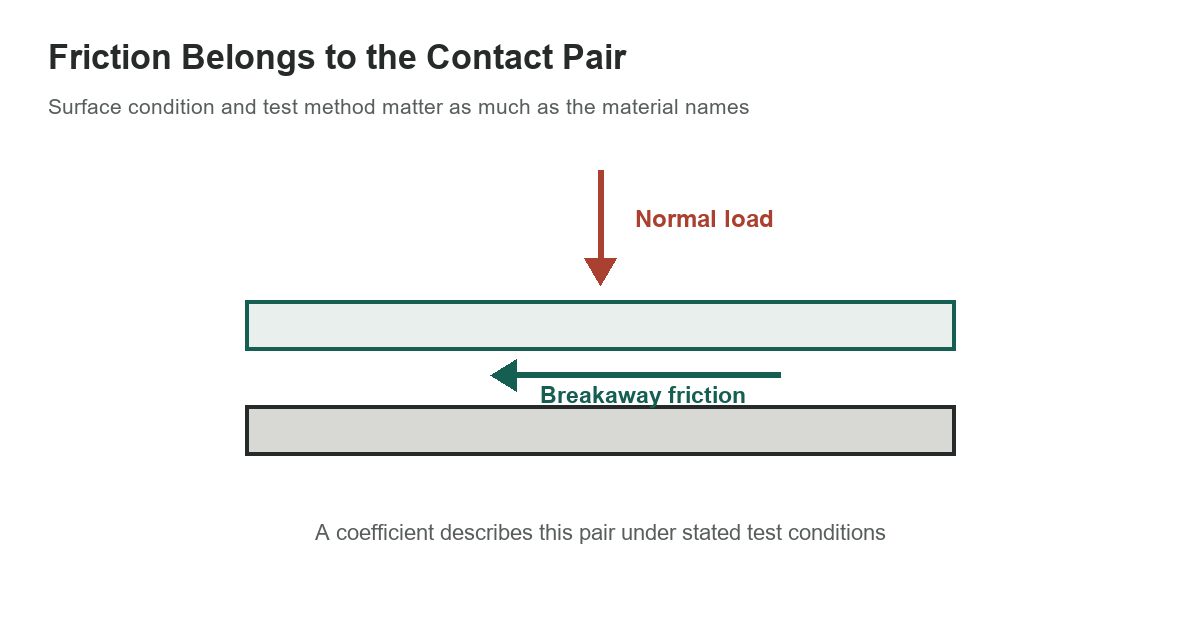
Static-friction coefficients describe a tested contact pair, not a permanent property of one material. The selected nonmetallic examples below come from an older reference and are useful mainly for seeing how widely reported values can differ. They are not modern design allowables, guaranteed material characteristics or a substitute for testing the actual surfaces.
[gs_table id=”11226″]
Keep the scope of the numbers visible
The selected values come from Machinery’s Handbook, 31st edition, Table 2, which credits Bowden and Tabor’s The Friction and Lubrication of Solids and labels the conditions “clean” and “lubricated.” It does not define the glass type, metal grade, surface roughness, lubricant, humidity, contact pressure or conditioning time for each row. These historical examples are not design values.
The values are therefore best read as historical examples, not as recommended coefficients. A broad interval, such as the listed glass-on-glass lubricated range, is a reminder that a single material name cannot uniquely predict friction. Even a narrow-looking value may have been measured with a method and surface state unlike the component in front of you.
Separate static from sliding friction
Static friction describes the force needed to initiate motion. Kinetic friction describes resistance after sliding has begun. A value for one should not be substituted for the other without a method and application basis. For a simple block model, the limiting static friction estimate is F = μN, where N is the normal load; the actual static force can be lower until impending motion occurs.
That equation is a useful introductory model, not a universal prediction for a complex interface. Adhesion, deformation, vibration, nonuniform pressure, surface films and local slip can matter. If friction controls holding capacity, positioning, braking or safe support, a favorable handbook number should not be used as the design basis.
Choose a test that resembles the use
ASTM G115-24 is a current guide for selecting friction measurement methods and reporting the tribosystem details needed to judge whether results apply. ASTM D1894-24 is narrower: it addresses static and kinetic friction testing of plastic film and sheeting under specified conditions. Do not assume a film test automatically applies to a thick molded part, a coated component or a different geometry.
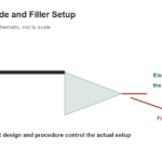
A meaningful test plan identifies both members of the pair, grade and orientation, surface preparation, coating, lubricant, normal force, contact geometry, temperature, humidity, dwell time, speed and measurement method. Record repeated results and variation, not just a single peak. Replicates can expose sensitivity to specimen preparation or test timing.
Use the right article for the material question
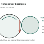
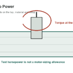
This page focuses on selected nonmetallic pair examples. The separate steel friction reference covers a few steel and metal combinations and explains the same caution from a different material scope. For a friction-wheel power calculation, see the friction-wheel horsepower examples; that page addresses drive power, not a universal material coefficient.
Polymer families also vary with grade and conditioning. The selected engineering-plastics comparison discusses grade-specific properties, but its strength data should not be treated as a friction coefficient for an untested pair.
Polymer friction is especially sensitive to grade and test configuration. Fillers, counterface material, transfer films, load and speed can change the result. A generic value for “nylon” or “PTFE” cannot specify the behavior of an arbitrary formulated product. Check the material supplier’s test data and whether its counterface and conditions match the application.
When to avoid generic values
If a part must resist slip reliably, use an engineered mechanical restraint or a qualified design method rather than relying solely on a handbook coefficient. If controlled motion is required, test across the expected range of load, environment, wear and dwell. Establish an acceptance criterion and account for variation, aging and contamination.
Use these historical entries to frame questions and plan a suitable test, not to certify a joint. ASTM’s reporting guidance and application-specific test methods provide a better route when friction is a controlling engineering property.
Sources: ASTM G115-24, ASTM D1894-24 and Machinery’s Handbook, 31st edition, Table 2, printed page 173.