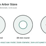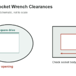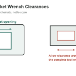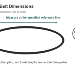
A shell reamer mounts on an arbor, and torque passes through the arbor’s driving lugs into matching slots in the reamer. Those interfaces must match; a close-looking fit is not a substitute for checking the dimensions and the tooling manufacturer’s instructions. The reference below gives selected historical dimensions for arbor sizes 4 through 9, not a complete interchangeability approval.
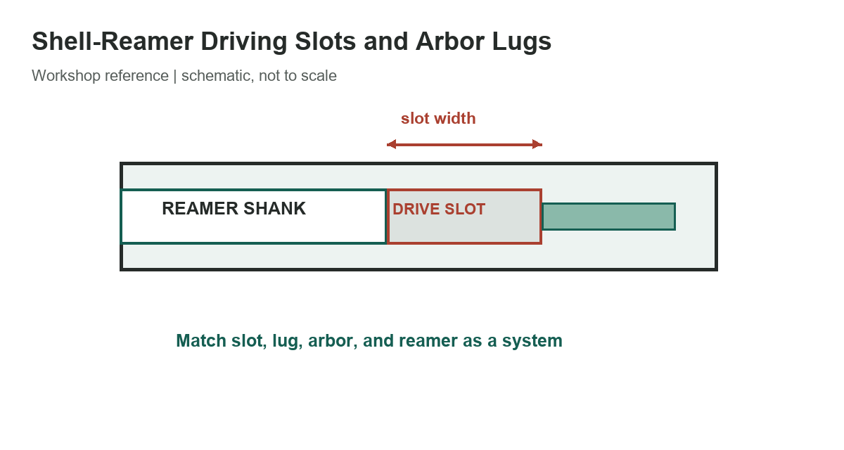
Read the interface dimensions
W and J describe the reamer’s driving slot width and depth. L and M describe the arbor lug width and depth. The reamer-hole diameter is measured at the large end of its tapered mounting hole. Confirm which dimension is being measured and the datum used before comparing a physical part with a drawing. Do not infer an arbor size from the reamer-hole diameter alone.
[gs_table id=”10756″]
The table is a limited selection from an older reference. ASME identifies B94.2-1995, reaffirmed as S2025, as its standard covering reamer nomenclature, types, sizes, and tolerances; the standard remains in effect on stabilized maintenance. This small comparison is not a replacement for the controlled standard, a current arbor drawing, or the manufacturer’s fit guidance. Buy or machine the arbor to the exact interface specification required by the tool.
Check the complete fit before cutting
Start by identifying the reamer type and size, the arbor type, and the intended workholding arrangement. Inspect the taper and large-end diameter, the drive slots, the arbor lugs, and any retaining or drawbar feature. Check for burrs, peening, fretting, chips, cracks, and evidence that a previous setup was run loose. A damaged lug or slot can concentrate load, spoil concentricity, and allow the tool to slip under torque.
Clean mating surfaces and verify that the reamer seats fully without rocking. Confirm that the drive features engage across their intended faces rather than touching only at an edge. Keep the spindle, arbor, and workpiece aligned according to the machine and tool instructions. Runout, overhang, workholding stiffness, cutting conditions, and the reamer’s condition all affect hole quality; changing one interface dimension cannot compensate for a poor setup.
These dimensions describe geometry, not cutting parameters. The appropriate speed, feed, coolant, and allowance depend on the reamer material and construction, workpiece alloy, hole depth, machine rigidity, and required finish. Follow the current tool maker’s data. Stop if the assembly has uncertain fit, visible damage, unusual vibration, or a tendency to pull out of its seat.
Measure without confusing the labels
Use a suitable micrometer, gauge, or inspection method for each feature. Measure slot width and lug width at several points if wear or deformation is suspected. Check depths from the correct face, and avoid using a chamfer or radius as the measurement surface. A caliper may be useful for an initial check, but tight fits and worn features require appropriate inspection tools and tolerance information.
Record the arbor size, reamer identification, interface measurements, standard or drawing revision, and inspection result. If the machine shop cannot establish a reliable match, contact the reamer or arbor manufacturer with the tool markings and measured dimensions. Do not force a mismatched tool or grind drive features to make it fit; obtain a compatible arbor or have the interface reviewed by a qualified tooling specialist.
- Identify the exact reamer and arbor types.
- Check taper, slot, lug, and retaining features together.
- Inspect for wear, burrs, cracks, and poor seating.
- Use the current controlled drawing or standard for final fit.
Browse the size-chart library, compare threading tool options, and review socket size identification for other shop measurement references.
References
See ASME’s current listing for B94.2, Reamers. Use the standard and the reamer/arbor manufacturer’s controlled drawings for final selection.