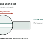
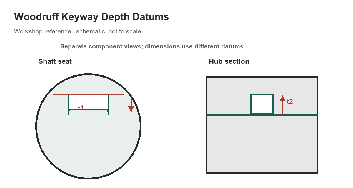
A Woodruff key fits partly into a curved shaft seat and partly into a straight keyway in the hub. These are two different cuts with different depths. The selected chart lists nominal shaft-seat depth t1 and hub-slot depth t2 for six metric key sizes published for DIN 6888. It is a focused machining reference, not a complete key-selection or tolerance table.
Selected shaft-seat and hub-slot depths
Read the first column as key width by nominal disc diameter. For example, a 4 × 13 mm key corresponds to a nominal shaft-seat depth of 5.0 mm and hub-slot depth of 1.4 mm in the selected supplier chart. Do not swap t1 and t2: t1 is measured at the shaft seat, while t2 is the hub slot depth measured from the hub bore surface.
[gs_table id=”11138″]
Keep the dimensions attached to the correct surface
The curved key sits below the shaft surface, while its top projects into the hub slot. A key that appears to fit the shaft cut may still be too high or low for the hub. The required fit, key width, depth tolerance, shaft diameter, key material, and application all matter. The table intentionally omits width tolerances, key height tolerances, corner radii, and shaft-diameter ranges; consult the complete current drawing or standard before machining.
DIN Media lists DIN 6888:2022-03 as the current German edition for Woodruff key dimensions and application. The original handbook page reviewed for this article cited a withdrawn 1996 ANSI/ASME edition, so its historic dimensions were not used as the current source. The selected t1/t2 values are taken from the supplier’s DIN 6888 table and are not a reproduction of the full standard.
Measure from the right datum
On a shaft drawing, the seat depth is normally referenced from the shaft’s local surface toward the curved pocket. On the hub drawing, slot depth is measured from the bore surface toward the outside diameter. A drawing may use different datums or specify a different fit series. Confirm the dimension arrows and tolerance block rather than inferring the measurement from a key’s overall height.
The two depths describe where the key sits, not the full key height or its disc diameter. A depth is measured from a stated surface into the component; changing the datum changes the apparent number. The key’s nominal width determines the side fit, while its curved diameter controls the seat shape. A cutter must match the specified keyway width and profile, and its runout or wear can affect the finished cut. Do not add t1 and t2 and treat that sum as a single machining depth.
The values are metric nominal dimensions. A drawing may specify a tolerance class, a close or free fit, a particular application series, or a different standard. The chart does not state those tolerances. Confirm the standard edition and the supplier’s current product drawing before production, especially when replacing a worn key or matching an existing hub. If a selected size is unavailable, do not round to the next row without checking shaft diameter and hub engagement.
Before cutting, verify the key designation, shaft and hub material, fit, cutter diameter, cutter width, and the drawing revision. Do not machine to these selected values if the assembly drawing specifies another standard or depth. For the key dimensions and shaft-diameter guidance, see our metric Woodruff key size chart. For additional dimensional references, see the fractional-inch to millimeter lookup and clearance-hole chart; those tables do not define Woodruff keyway fits.
References
- DIN Media identifies DIN 6888:2022-03 as the current Woodruff-key dimensions and application edition.
- The supplier’s selected DIN 6888 table lists key width, disc diameter, shaft-seat depth, and hub-slot depth.
- McMaster-Carr’s DIN 6888 listing describes Woodruff-key applications near shoulders and on tapered shafts.