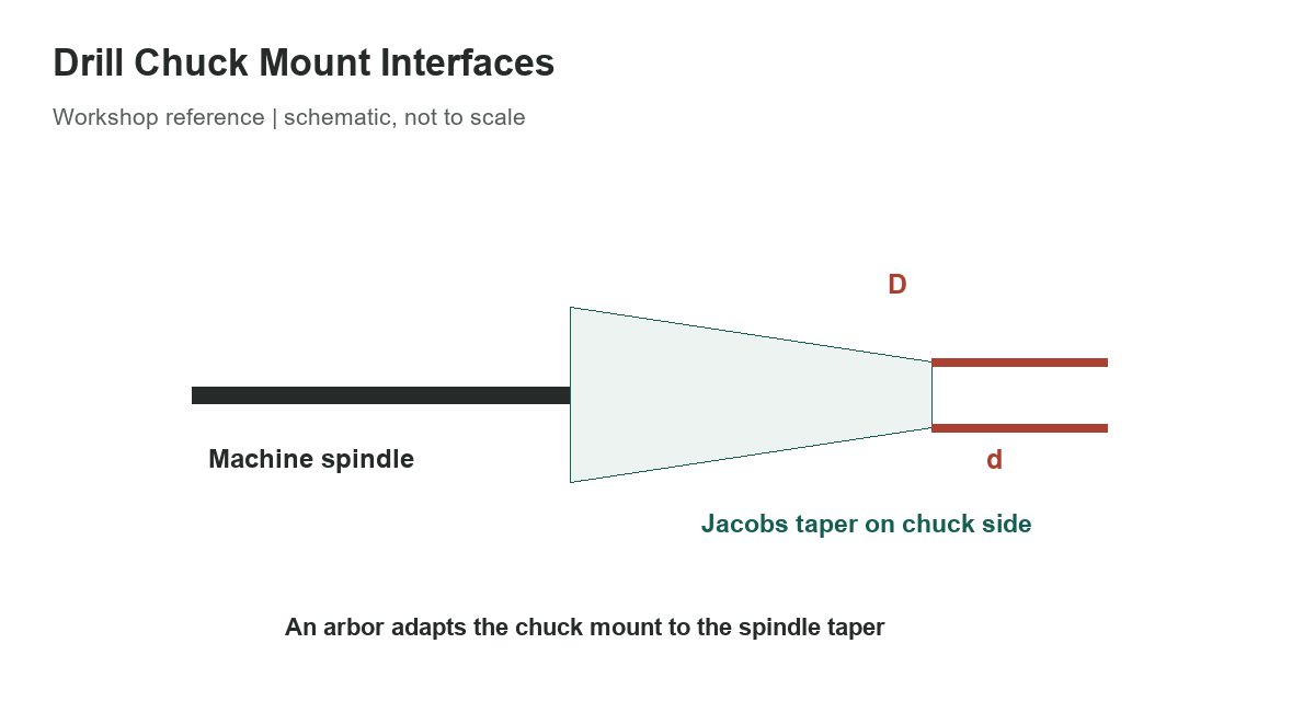
A drill chuck mount may use a Jacobs taper, a threaded mount, or a straight shank. Those are chuck-side interfaces; the machine spindle may use a Morse taper or another mount. An arbor joins the two interfaces. Match the actual mount names and dimensions on both ends instead of assuming that two tools labeled “taper” will fit each other.
Jacobs taper dimensions
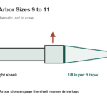
The selected chart lists the Jacobs taper number, large-end diameter D, small-end diameter d, reference length l1, and taper per diameter. Dimensions are in inches. The manufacturer’s technical sheet notes that the Jacobs series contains both a No. 2 Short and a separate No. 2 taper. They share a small-end diameter and taper ratio, but have different large-end diameters and lengths. Keep those two designations distinct when measuring or ordering.
For example, the No. 1 reference has D 0.3840 in, d 0.3334 in, and length 0.56525 in. The No. 2 Short is shorter than No. 2, even though both list d as 0.4876 in. The taper-per-diameter field describes the change in diameter per foot of taper, not the angle in degrees. It is not a substitute for checking the actual taper over its engagement length.
[gs_table id=”11101″]
Separate the chuck mount from the spindle
Jacobs describes an arbor as a chuck-mounting device that adapts a standardized chuck mount to a machine spindle taper. A sleeve can adapt an arbor when the machine spindle requires a larger taper than the arbor provides. Jacobs also lists standard threaded mounts and straight mounts, which should not be mistaken for Jacobs taper sockets. The machine-side taper might be Morse while the chuck-side taper is Jacobs; the part name alone does not tell you which side a dimension describes.
Before selecting an arbor, record the chuck model and its mount, then identify the spindle taper from the machine manual or marking. Confirm both ends, the arbor length, and any drawbar or retention requirement. A close-looking diameter is not enough: taper angle, gauge length, contact, and retention all affect fit. Do not force a mismatched arbor into a chuck or spindle. When inspecting a used arbor, check the taper for raised burrs, dents, rust, or polishing that suggests poor contact. Clean the surfaces before measuring, and compare the component’s stamped designation with the machine documentation. A caliper reading at only one point cannot identify the taper series reliably.
The benchtop drill-press guide covers the machine choice, while the drill-bit size chart and taper-shank jobber reamer reference cover cutting-tool sizes. Those tools use their own interfaces; their dimensions do not define a chuck mount.
Limits of the reference values
Jacobs says the values classify normal taper dimensions and are advisory for new applications; it asks users to contact its engineering department for current specifications. The sheet also identifies two interpolated taper numbers, 33 and 6, and the additional No. 2 Short. This chart omits the threaded and straight-mount tables and should not be used to infer an unlisted mount or interchangeability.
For a replacement, compare the component marking, inspect the mating surfaces, and use the chuck or arbor maker’s current drawing. If the mount is unidentified, have it measured over a known length with appropriate taper gauges or shop equipment. Avoid relying on a single caliper reading at one end of a taper. For a new machine design or a safety-critical spindle assembly, obtain the current manufacturer specification before release.
Use the table to narrow an identification, not to approve a spindle assembly. It contains selected reference dimensions and does not provide retention force, runout, speed rating, or load capacity.
References
- Jacobs technical information distinguishes the two No. 2 tapers and labels D, d, l1, and taper per diameter.
- Jacobs technical support explains arbors, sleeves, Jacobs taper mounts, threaded mounts, and Morse-taper spindle interfaces.