Quick answer: Running boards attach through a vehicle-specific structural system, not a method chosen by convenience. Common systems use factory threaded rocker holes, clip or U-nuts in documented body openings, pinch-weld braces, body-mount or frame brackets, or purpose-designed threaded inserts. The board then bolts or slides onto those brackets through a separate interface. Powered boards add linkage arms and wiring. Adhesive tape is suitable for trim, pads, seals, or protective film when specified, but never as the load-bearing attachment for a passenger step.
Separate The Three Parts Of The Attachment
“How does the running board attach?” can refer to three different joints. First is the vehicle-to-bracket attachment, which transfers passenger load into approved body, rocker, body-mount, or frame locations. Second is the bracket-to-board attachment, which may use channel bolts, track nuts, studs, clamps designed by the manufacturer, or brackets welded to the board at the factory. Third is the non-structural trim attachment, such as a step pad, end cap, cover, light, or protective strip.
Confusing these joints creates bad advice. A board with factory-welded brackets does not imply that an installer should weld to a vehicle. A trim strip attached with tape does not prove that tape can carry a person’s weight. A clamp-shaped plate inside a rocker opening is not permission to place a generic clamp anywhere on a frame rail.
| Joint | Typical documented hardware | Controls the method |
|---|---|---|
| Vehicle to bracket | Factory bolt, threaded hole, clip nut, nut plate, insert, body-mount hardware | Exact vehicle application and bracket kit |
| Bracket to board | Track bolt, channel nut, stud, flange bolt, proprietary clamp | Board family and bracket design |
| Powered linkage to board | Position-specific arms, pivots, motors, and fasteners | Powered-system generation and side |
| Trim or tread component | Clips, screws, molded tabs, or specified adhesive | Component instructions; not structural capacity |
Rocker-Panel And Pinch-Weld Brackets
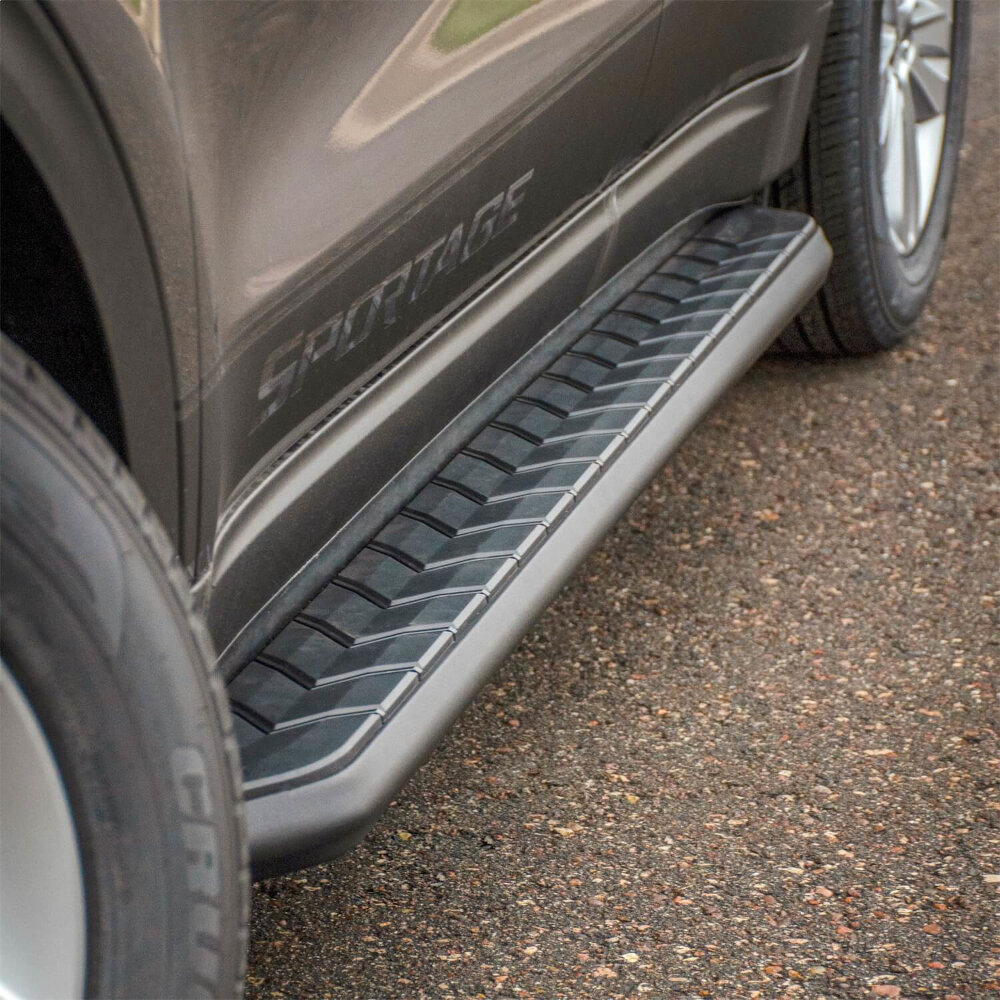
Many vehicle-specific kits mount near the rocker panel. Depending on the application, the bracket may use factory threaded holes, welded nuts, clip nuts placed through access openings, or nut plates positioned behind sheet metal. A secondary flange may brace against existing pinch-weld holes. The bracket geometry spreads load across the locations selected by the kit engineer.
Do not describe every rocker-mounted board as “bolted to thin sheet metal.” The complete bracket can engage several surfaces, and the exact fasteners matter. At the same time, do not assume a visible hole is structural. Match every hole, plug, stamped bracket position, and driver/passenger orientation to the current instruction sheet.
Body-Mount And Frame-Mount Systems
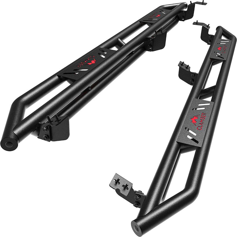
Some heavy-duty steps, sliders, or older truck kits use body-mount bolts or dedicated frame brackets. These attachments can place load differently from rocker-mounted boards and may affect ground clearance. A body-mount bolt can also control body isolation and alignment, so loosening or replacing it requires the exact procedure, support method, hardware, and torque from the kit and vehicle documentation.
A true frame-mounted system uses brackets engineered for specific frame geometry and nearby components. It is not a generic invitation to drill or weld onto the frame. Fuel and brake lines, wiring, boxed sections, heat shields, high-voltage components, corrosion protection, and manufacturer restrictions all matter. If the documented attachment is absent or modified, stop and consult the kit manufacturer or a qualified fabricator.
| Vehicle-side system | How to recognize it | Main caution |
|---|---|---|
| Factory threaded rocker points | Manual identifies welded nuts or threaded inserts | Clean threads and avoid cross-threading |
| Clip/U-nut or nut plate | Hardware enters a documented access opening | Correct orientation and retention are essential |
| Rocker plus pinch-weld brace | Bracket uses both inner rocker and lower flange points | Do not crush or distort the pinch weld |
| Body-mount bracket | Bracket shares a documented body-mount location | Follow support, bolt replacement, and torque procedure |
| Frame bracket | Kit names a frame location and bracket geometry | Inspect line clearance and drilling restrictions |
| Purpose-designed threaded insert | Manual specifies insert type, hole, and installation tool | An improvised insert may spin or pull out |
Board-To-Bracket Interfaces
Once vehicle brackets are loosely installed, the board often attaches through a lower track or channel. Sliding bolts or nuts allow fore-aft adjustment before final tightening. Other boards use fixed studs, dedicated holes, or a proprietary cradle. Position every fastener in the manual’s range and keep the board supported until enough hardware is engaged to prevent rotation.
Install all brackets and board fasteners loosely before alignment unless the instructions explicitly say otherwise. Fully tightening the first bracket can pull the remaining brackets out of position or twist the board. After aligning to the door openings and checking body clearance, apply the separate vehicle-side and board-side torque specifications.
Pre-Welded Brackets Versus Welding To The Vehicle
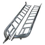
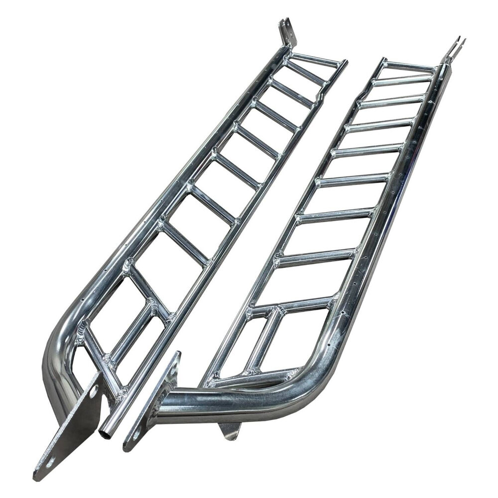
Some step assemblies arrive with brackets welded to the board or tube. ARIES, for example, describes vehicle-specific Rocker Steps with pre-welded brackets. Those welds were part of the product’s design and manufacturing process; the installer still attaches the assembly to documented vehicle points.
Welding a bracket directly to a vehicle is a different operation. It can affect heat-treated frame material, corrosion coatings, wiring, fuel systems, electronic modules, and crash behavior. It also makes removal and inspection harder. Only use a weld-on design when the vehicle and product engineering explicitly allow it and a qualified fabricator follows the relevant repair or body-builder procedure. Do not convert a bolt-on kit to weld-on because holes do not align.
Why Generic Clamp-On Advice Is Misleading
Some mounting hardware wraps around or bears against a structural feature, but it is still an engineered part of a vehicle-specific kit. A nut plate placed inside a rocker opening, U-bolt around a documented member, or track clamp under a board is not equivalent to an arbitrary hardware clamp. Shape, material, contact area, anti-rotation features, and torque determine whether it can carry repeated passenger loads.
Do not transfer a clamp-mounted board from one vehicle to another unless the manufacturer lists the same bracket kit for both applications. A clamp that feels tight during installation can move, crush a flange, abrade coatings, or loosen under cyclic loading.
Adhesive Has No Structural Passenger-Load Role
Automotive adhesives and tapes can be appropriate for decorative trim, rubber tread inserts, end-cap seals, light strips, anti-rattle pads, paint-protection film, or temporary positioning when the product instructions specify them. They are not a substitute for structural brackets and fasteners on a board intended to support a person.
Surface preparation, temperature, cure time, and adhesive chemistry still matter for non-structural parts. Keep adhesive and dressings away from the stepping surface unless the component manufacturer permits them. If a product marketed as a running board relies only on tape to attach the load-bearing board to painted bodywork, do not use it as a step.
| Attachment claim | Safe interpretation | Red flag |
|---|---|---|
| “No drill” | Uses documented existing holes or mounts | Seller provides no vehicle-specific bracket instructions |
| “Clamp on” | Manufacturer supplies engineered clamps for listed application | Universal clamps placed by eye |
| “Welded brackets” | Brackets were welded to the board during manufacture | Installer is told to weld an unapproved frame location |
| “3M tape included” | Likely for trim, pads, or protective pieces | Tape is described as carrying passenger load |
| “Universal fit” | Board profile may be universal with separate application brackets | No documented bracket kit for the vehicle |
Powered Running Boards Add Moving Attachments
Powered systems use front and rear linkage assemblies instead of simple fixed brackets. Arms can be side- and position-specific, and their pivot geometry controls deployed height and retracted clearance. The system also adds motors, a controller, wiring, fuses, lights, and door or vehicle-network inputs. Treat the complete kit number, bracket number, and electrical revision as one application.
Check that linkages move without binding before relying on the motors to force alignment. Route wiring only where the manual shows, away from exhaust, suspension, steering, driveshafts, sharp edges, and pinch points. Never mix unidentified powered-board components because the connectors appear to fit.
How To Verify An Attachment Before Stepping On It
| Verification | Pass condition | Stop condition |
|---|---|---|
| Application | Exact vehicle and kit appear in current documentation | Fit is based only on board length or appearance |
| Mounting points | Every point matches the instruction diagrams | Missing, corroded, damaged, or modified structure |
| Hardware | Correct quantity, grade, coating, and orientation | Improvised or mixed fasteners |
| Alignment | Board clears body and doors and sits consistently | Bracket twist or body contact |
| Torque | Applied by joint from the exact manual | Universal internet value or impact-only tightening |
| Load check | No movement, flex, noise, or fastener shift | Rocking, popping, bending, or slipping |
Reinspect after the first short drive and at the manufacturer’s stated interval. Also inspect after impacts, off-road use, or winter exposure. Stop using the board when a bracket cracks, a mounting point deforms, hardware loosens repeatedly, or corrosion compromises the load path.
Related GarageSanctum Guides
- Follow a safe Chevy application-first installation workflow.
- Compare frame and rocker mounting paths.
- Identify documented running-board hardware.
- Identify an unknown board, bracket, or kit.
- Choose a professional installer for structural or powered systems.
- Compare OEM accessory and aftermarket attachment support.
Source Notes
- Westin rocker and pinch-weld installation instructions illustrate factory openings, clip nuts, bracket orientation, loose assembly, alignment, and kit-specific torque.
- Westin multi-generation truck instructions show how attachment hardware and existing holes can differ even within one product application family.
- ARIES Rocker Step documentation distinguishes factory pre-welded board brackets from the vehicle-side installation.
- ARIES running-board system overview documents vehicle-specific no-drill bracket systems rather than universal placement.
- ARIES ActionTrac application guide separates board, bracket, and complete-kit numbers by vehicle.