A pipe entrance creates a local energy loss as fluid contracts and accelerates into the line. The coefficient K_E represents that entrance effect for a stated geometry and method. The selected values below are not general pipe-friction factors; use them with the inlet shape and velocity reference that match the source equation.
[gs_table id=”11280″]
Use the entrance-loss equation
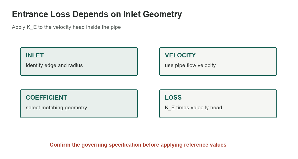
The source gives h_L = K_E v_o squared/(2g), where h_L is head loss, v_o is the velocity inside the pipe, and g is gravitational acceleration. In SI units, velocity in meters per second and g in meters per second squared produce head in meters. In customary units, keep feet and seconds consistent.
If you are calculating pressure drop instead of head, convert using the fluid’s specific weight and maintain a consistent pressure unit. The coefficient itself is dimensionless. A unit mistake in velocity or using tank approach velocity instead of pipe velocity can dominate the result.
Match the entrance geometry
A rounded inlet is described by the ratio R/Do, where R is the radius at the entrance and Do is the pipe’s outside diameter as labeled in the source. The listed rounded cases show lower coefficients as the radius ratio increases. Use the same geometric definition and ratio convention; do not replace it with a radius-to-inside-diameter ratio without confirming equivalence.
The square-edged, chamfered, and inward-projecting entries are separate conditions and do not use the rounded-inlet ratio column. A pipe projecting into a tank is not the same geometry as a flush entrance. Photograph or measure the actual connection when the loss estimate is sensitive to its shape.
Interpret the coefficient with care
The table’s values are representative reference coefficients. Actual loss may depend on Reynolds number, inlet condition, edge quality, flow distribution, nearby fittings, and the source’s adopted method. Crane-based references commonly show a sharp-edged flush entrance near K = 0.5 and an inward-projecting entrance near K = 0.8 to 1.0 depending on the chosen convention.
Do not merge values from different references merely because they share the symbol K. Some sources define a coefficient against pipe velocity head, while others use a different reference velocity or equivalent-length method. Confirm the definition before comparing or combining coefficients.
Separate entrance loss from pipe friction
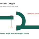
Entrance loss is a local loss at the pipe boundary. Distributed friction along a straight run is calculated separately using a friction model and the pipe length, diameter, roughness, and flow regime. Bends, valves, tees, exits, expansions, and contractions may each contribute additional local losses.
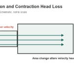
For a system model, document each component and reference velocity, then sum losses without double-counting. The site’s pipe expansion and contraction head-loss guide covers area-change losses, while the Hazen-Williams coefficient reference is a friction-method input and not an entrance coefficient.
Check how the system operates
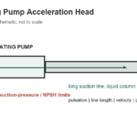
A suction line, gravity-fed line, and pressurized discharge can have different controlling conditions even when the same entrance coefficient is selected. Evaluate the full energy balance between defined points, including elevation, pressure, velocity, pump contribution, and all relevant losses. For pump suction, inadequate available head can cause performance problems or cavitation.
This selected table is not a pump-sizing result. Use the required design flow, fluid properties, temperature, pipe internal diameter, and fitting geometry in a recognized method. For regulated water, fire-protection, gas, or process systems, follow the applicable code and authority requirements instead of a generic chart.
Measure rather than guess
A sharp corner can be rounded by fabrication, corrosion, a molded bellmouth, or a reducer; visual labels alone may not describe the actual entrance. Check whether the pipe is flush with the tank wall or projects into it, whether a screen or strainer is installed, and whether the inlet is partially obstructed.
For a consequential design, validate the model against the equipment manufacturer’s data or measured operating conditions. The pipe-size reference helps identify nominal and outside dimensions, but hydraulic calculations generally require the actual internal diameter for the selected pipe schedule.
Sources: Crane TP-410 entrance coefficient examples, Pipe entrance losses with Crane method, Original handbook extraction