Parting-tool width is not a universal function of bar diameter. A narrow blade removes less material but may be unsuitable for the required cut depth, work material, feed, or machine setup. A wider tool can offer a different geometry or reach, yet it also changes cutting forces and kerf. The old stock-diameter lookup in the historical handbook should not be treated as a modern rule for choosing a blade.
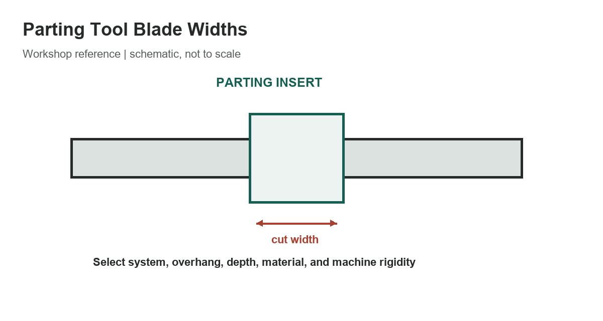
Start with the tool system
Current insert-based systems publish their own work-diameter, cutting-width, and depth ranges. The table gives selected ranges from Sandvik Coromant’s 2026 parting and grooving catalog. They are examples of system capability, not interchangeable dimensions: the holder, blade, insert, grade, overhang, and machine interface must all match.
[gs_table id=”10764″]
For a current job, identify the exact parting system and its catalog revision. Confirm the selected insert’s width and geometry, maximum cutting depth, work diameter, and compatible blade or holder. A system’s broad family range does not mean that every width is offered for every depth or material. Use the maker’s tool-specific selection table and technical documentation for the actual combination.
What sets a practical blade width?
Part geometry and downstream handling matter. The width must clear the parting groove, leave the required shoulder, account for parting allowance, and avoid colliding with a feature or fixture. Very small parts may call for a narrow insert, but a fragile part can also be sensitive to deflection or cutoff forces. If the part is being cut from bar, consider how the remaining stub and material waste affect the operation without compromising stability.
Material influences chip formation, heat, wear, and cutting force. Tough or work-hardening alloys, gummy materials, and interrupted surfaces may require different insert geometry and cutting data. The same blade width can perform differently with a different grade, coolant strategy, or chip-control feature. Follow the maker’s recommended speeds and feeds for the workpiece alloy and operation instead of transferring a setting from another material.
Machine and setup rigidity are equally important. Check spindle and toolholder compatibility, blade height, clamping, tool center height, workpiece support, and the permitted overhang. Excessive overhang increases deflection and vibration risk. For bar work, use the correct support and guarding, and make sure the cutoff part can be safely captured. Tool setup guidance often limits clamping geometry; the catalog and machine instructions control the exact requirement.
Use a selection sequence
- Identify the work material, diameter, cut depth, and part geometry.
- Select a tool family designed for that diameter and depth.
- Choose an insert width and geometry compatible with the required groove and cutoff.
- Verify holder, blade, insert, overhang, and machine interfaces.
- Apply the current maker’s speed, feed, coolant, and chip-control guidance.
Do not infer an acceptable width from a legacy stock-diameter table alone. Test the setup under controlled conditions, inspect the cut face and chip form, and adjust only within the maker’s limits. Stop if the blade chatters, deflects, binds, or shows damage. Production settings and safety procedures belong to the responsible machinist and process engineer.
Part width is also distinct from the insert’s cutting-edge width and the final kerf left in the workpiece. Check the catalog definition for the chosen insert, including whether dimensions refer to nominal width, maximum depth, or a particular holder. Tolerances, insert corner radii, and the way the tool is set on center can affect the resulting groove. Measure a trial cut before committing a setup to a production batch.
Browse GarageSanctum’s tool guides, see the reference chart library, and compare shop hand-tool selection.
References
See Sandvik Coromant’s parting and grooving guidance and its current catalog for the selected system dimensions. Confirm current catalog availability before ordering.