Grinding wheels are not interchangeable just because their diameter is similar. Shape, thickness, bore, bond, operating speed, guard, and machine capacity all matter. This metric reference presents five selected shape-and-operation combinations from the handbook’s table based on ANSI B74.2-2003. It is a compact orientation chart, not a purchase specification or a complete catalog.
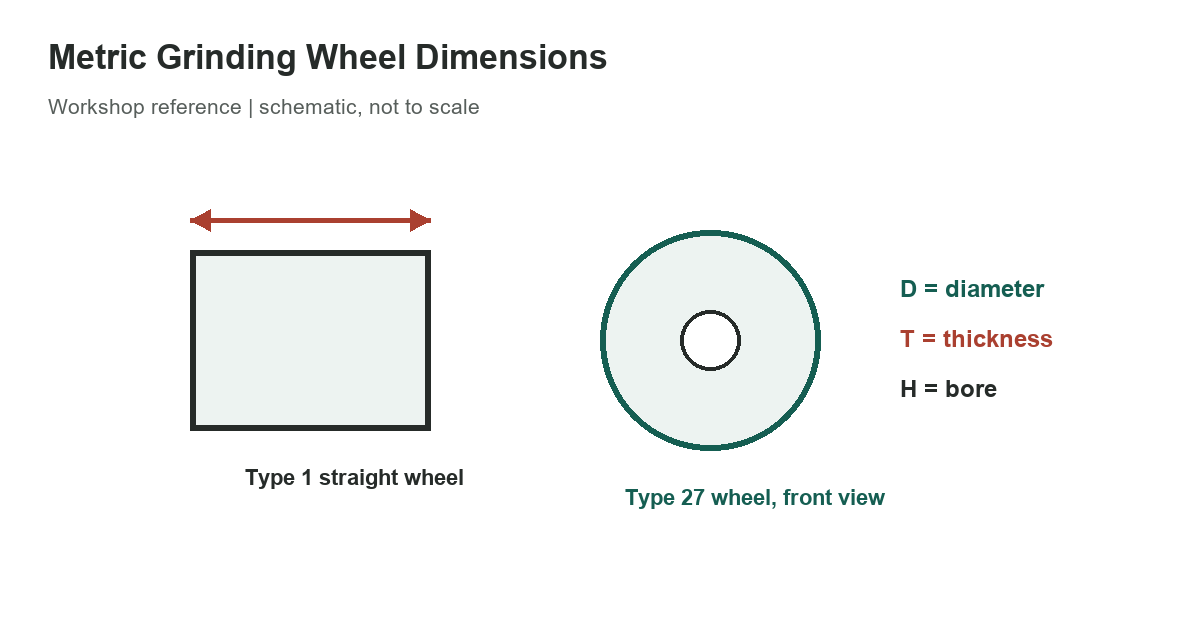
Read D, T, and H
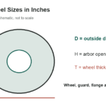
D is the nominal outside diameter, T is thickness, and H is the bore or mounting opening. All values in the table are millimeters. A range means the referenced shape/application combination includes a range of nominal dimensions; it does not mean every combination of the three endpoints is available. “127 or 304.8” and similar entries are discrete alternatives, not continuous ranges.
For example, the Type 1 internal-grinding row lists D from 6 to 100 mm, T from 6 to 50 mm, and H from 2.5 to 25 mm. The type 7 regulating-wheel row is a different cylindrical-grinding use and has different dimension ranges. Do not carry one row’s bore or thickness values into another wheel shape.
[gs_table id=”11076″]
Match the wheel to the machine
Before mounting, compare the wheel marking and manufacturer drawing with the grinder’s spindle, flanges, guard, and maximum permitted speed. A dimensional fit alone does not prove that the wheel is rated for the machine or for the intended work. Cutting-off and grinding faces are not automatically interchangeable, and a wheel marked for a specific operation must be used as directed.
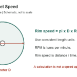
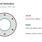
The standard listed by the Unified Abrasives Manufacturers’ Association is UAMA B74.2-2003, the shapes-and-sizes standard represented by the handbook table. The source is old enough that product availability and standards may change; ask a manufacturer for the current drawing rather than treating this selected extract as a current stock list. The separate inch-series Type 27 product examples describe specific Norton products, not the general metric ranges shown here. For wheel speed calculations, see the RPM and surface-speed guide, or compare abrasive choices in the grinding-wheel selection guide.
Use ranges carefully
Wheel dimensions are only one part of safe selection. OSHA’s abrasive-wheel rules address machine guarding, mounting, inspection, and operating conditions. Check the rules that apply to your workplace and the machine manufacturer’s instructions. Never infer a safe speed from diameter alone: the wheel’s marked maximum speed and the grinder’s actual spindle speed control.
Do not use the table to calculate a speed rating, approve a wheel, or substitute a different bore. Confirm that the exact wheel type, mounting arrangement, and maximum operating speed agree with the current product label and machine manual. If the selected range does not contain the machine’s required dimensions, consult the wheel supplier rather than modifying the wheel or flange.
A dimension range is a standards reference, not a promise that a manufacturer sells every diameter, thickness, and bore combination. Some combinations may be made only for a particular machine or operation. Record the wheel’s full designation and check its packaging or product drawing; the shape number by itself does not describe the abrasive, bond, grade, reinforcement, or speed limit.
Measure the machine spindle and approved flanges with suitable tools, but do not use a measurement to override the marked wheel bore or the manufacturer’s mounting requirements. A loose fit, forced fit, improvised bushing, or mismatched flange can create a serious hazard. If a wheel is damaged, has an unreadable label, or does not match the machine manual, do not mount it.
The table also groups some sizes by operation, such as internal grinding or cutting off. That grouping helps narrow the search but does not make a wheel suitable for every material or feed. The wheel maker’s product recommendation and the grinder’s operating instructions determine the intended use.
References
UAMA lists B74.2-2003 as its shapes-and-sizes standard for grinding wheels. OSHA 29 CFR 1910.215 covers abrasive-wheel machinery in applicable workplaces. Neither reference replaces the wheel’s current manufacturer drawing, marked speed, or grinder manual.