An old tooling list may identify a drill by a British gauge number that is unfamiliar in a modern metric shop. A handbook appendix pairs selected legacy British drill sizes with recommended metric diameters. These pairs help decode historical records; they do not make a worn or marked drill a precision measuring standard. The table below shows selected examples only, while the site’s general drill chart serves current number, letter, fractional, and metric lookups.
[gs_table id=”11426″]
A gauge number is not a decimal diameter
British gauge designations form a historical size series. A larger gauge number in the selected part of the list generally corresponds to a smaller diameter, but the number itself is not a millimetre measurement and should not be converted by an assumed formula. Read the exact designation and the source’s recommended diameter as a pair.
The original table also contains rows whose recommended replacement is shown as a fractional-inch drill rather than a metric value. This article omits those rows instead of relabelling an inch fraction as millimetres. Letter designations and numbered gauges must also be kept in their own size systems. The metric column is a recommended replacement from the historical appendix, not an exact mathematical conversion of a drill’s measured diameter. A replacement can be close yet still produce a hole outside a drawing’s tolerance; confirm fit and process requirements rather than choosing by nearest number alone.
Use the cross-reference for old records
The 1959 appendix reproduced in the handbook says that the old British sizes had been superseded and were not for producing new drills. Its purpose is historical transition: a maintenance record, legacy fixture, or drawing may name a gauge size even when the replacement tool is sold by metric diameter. The twelve selected pairs are a compact aid for that identification task, not a complete conversion chart.
For a real hole, confirm the required finished diameter, fit class, material, operation, and tolerance from the drawing or process plan. The cutting tool’s label is only one input; runout, tool condition, work material, setup, and feed can affect the hole produced.
Choose a present-day drill deliberately
The site’s drill bit size chart organizes current number, letter, fractional, and metric designations and shows that close sizes are not automatically interchangeable. The large straight-shank drill dimensions and core-drill length reference address tool dimensions, not the historical gauge conversion itself.
Check the standard and the actual tool
BSI lists BS 328-1:1993, the later twist-drill specification, as withdrawn on May 22, 2026. That status is separate from the 1959 table reproduced here, but reinforces the need to check the current product standard and supplier catalog rather than assume an old appendix remains a production specification. Follow the drawing, current standard adopted by the organization, and drill manufacturer’s tolerances for a new part.
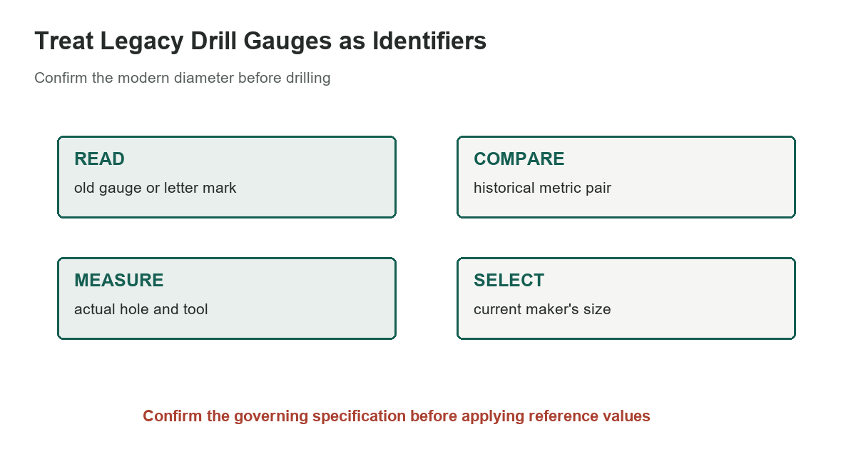
If a legacy size appears on a safety-critical or close-tolerance feature, do not substitute the nearest listed diameter by eye. Confirm the design intent with the responsible engineer, inspect the existing feature using an appropriate instrument, and document the chosen replacement size. For routine maintenance, record both the original gauge callout and the verified modern drill designation on the work order so another technician can trace the decision.
When to use the broader chart
Use this historical list to interpret an old British gauge callout. For ordering a new drill, checking a hole tolerance, or comparing ordinary number, letter, fractional, and metric sizes, start with a current tool catalog and the site’s general drill-size chart. Preserve the original designation in maintenance records, but write the verified modern diameter separately so later readers can distinguish the two systems.
Sources: Machinery’s Handbook, 31st edition, selected original page, BSI Knowledge: BS 328-1:1993 status