Quick answer: Install Ram running-board courtesy lights as a protected automotive circuit, not by connecting them to whichever factory wires are nearby. First confirm the truck’s exact model year, platform, cab, existing powered steps, and desired light behavior. Calculate the load, use wire sized for the circuit length and current, place a fuse close to the power source, and control the lights with a properly rated relay, documented auxiliary output, or vehicle-specific interface. Route wiring in loom away from heat, exhaust, sharp edges, suspension, and lift points, then seal every exterior connection.
Define The Ram And The Lighting Behavior First
Ram 1500, 1500 Classic, 2500, 3500, and chassis-cab trucks do not share one universal wiring layout. Model year, body generation, factory auxiliary switches, powered running boards, and body-control programming can change the available circuits. Record the VIN, year, model, cab style, and any upfitter equipment before buying parts or opening a harness.
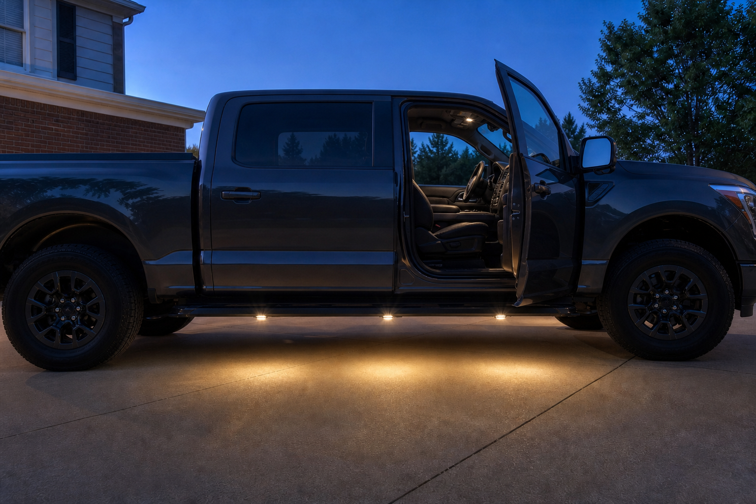
Also decide what the lights should do. Courtesy lights normally illuminate the step and ground when a door is unlocked or opened, then switch off after the vehicle’s courtesy-light delay. A manually controlled work light behaves differently. Decorative underglow may be restricted by color, brightness, location, flashing behavior, or use while driving. The electrical design and legal risk therefore depend on the intended behavior, not merely the LED strip’s length.
| Desired behavior | Preferred control approach | Important caution |
|---|---|---|
| On with door or unlock event | Vehicle-specific courtesy trigger controlling an isolated relay or interface | Do not load a body-control output directly without its documented capacity |
| On from factory auxiliary switch | Use the exact Ram Body Builder documentation for that truck | Output locations and ratings vary by model and configuration |
| Manual independent switch | Fused battery circuit with a rated relay and cab switch | Prevent accidental battery drain |
| Decorative underglow | Separate compliant accessory circuit | Confirm local color and on-road use rules before installation |
Courtesy Lights And Underglow Are Not The Same
For useful entry lighting, choose steady white or warm-white lamps aimed down at the tread and ground. The light should help occupants see the step without shining into other drivers’ eyes or making the truck resemble an emergency vehicle. Avoid exposed LED tape unless its environmental rating, adhesive system, end seals, and operating temperature are suitable for road spray and winter service.
Federal rules focus on required vehicle lighting and whether extra lamps impair its effectiveness; state and provincial rules can further regulate auxiliary lamps. A conservative courtesy installation uses no flashing effects, avoids red or blue exterior light, stays off while driving unless clearly permitted, and cannot obscure or confuse required lamps or reflectors.
Calculate Current Before Selecting Wire And Fuse
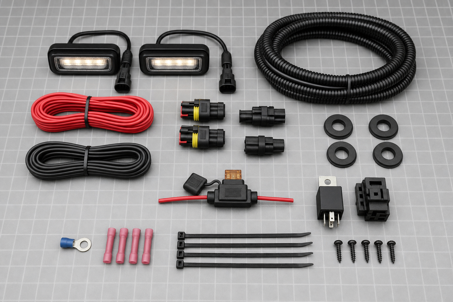
Add the rated wattage of every lamp that will operate together. Estimate current with amps = total watts / system volts. Four 3-watt pods draw about 1 amp at 12 volts, while two 18-watt strips draw about 3 amps before allowing for voltage variation and manufacturer tolerances. Use the product’s actual specification when available instead of estimating from strip length.
Wire size must account for circuit current, the complete out-and-back conductor length, allowable voltage drop, ambient temperature, bundling, and exposure. A long route from the battery to both cab sides can need larger wire than a short current table suggests. GarageSanctum’s 12-volt wire-gauge guide explains the inputs, while the lamp manufacturer or a qualified upfitter should make the final selection.
The fuse protects the wire, not the lamp’s advertised output. Select a fuse above the normal operating current but at or below the safe capacity of the smallest conductor and connector in that protected branch. Put the fuse close to the battery or approved power distribution point so an upstream short cannot leave a long unfused wire energized. See the automotive LED fuse-size guide for worked examples.
| Planning input | What to record | Why it matters |
|---|---|---|
| Total lamp load | Watts or measured current with all lights on | Sets the minimum circuit capacity |
| Circuit length | Positive and return path, not straight-line distance | Controls voltage drop and wire-size choice |
| Smallest component | Wire, connector, relay contact, and switch ratings | The fuse must protect the weakest conductor |
| Environment | Heat, loom bundling, road salt, and water exposure | Can reduce capacity and shorten component life |
Use A Protected Circuit Architecture
A robust layout is: approved battery or power-distribution source, then fuse, then relay contacts or a documented protected auxiliary output, then the lamps, with a sound return path. A low-current courtesy signal may control the relay coil or an appropriate interface. This separates the new lamp load from a sensitive body-control circuit.
Do not probe random door, dome-light, running-board, or trailer wires and leave a test lamp or accessory connected. Modern modules may use pulse-width modulation, switched ground, current monitoring, timed fade, or fault detection. An LED load or relay coil connected without a suitable interface can flicker, remain faintly lit, set faults, overload an output, or feed voltage back into a module.
If the truck has factory auxiliary switches, retrieve the exact Ram Body Builder or owner documentation by year, model, and option. Confirm the intended connection point, polarity, continuous or ignition-switched behavior, maximum load, existing fuse protection, and any programming required. A label that says AUX does not make every nearby wire interchangeable.
| Circuit part | Purpose | Common mistake |
|---|---|---|
| Source fuse | Protect the new supply conductor against a short | Installing it near the lamps instead of near the source |
| Relay or protected output | Switch the lamp current without overloading the trigger | Using an unknown factory wire as the full power feed |
| Trigger/interface | Follow courtesy or auxiliary-switch behavior | Assuming every trigger is a simple 12-volt positive signal |
| Ground/return | Complete the circuit with low resistance | Using a painted, corroded, or moving attachment point |
Plan Lamp Placement Before Drilling
Temporarily position the lamps with removable tape and power them from a separately fused test lead. Check the light pattern with every door open and closed, with the running board loaded, and from the viewpoint of approaching traffic. Illuminate the tread and ground rather than the painted rocker panel. Keep lamps where shoes, car washes, pressure washing, gravel, and curb contact are least likely to damage them.
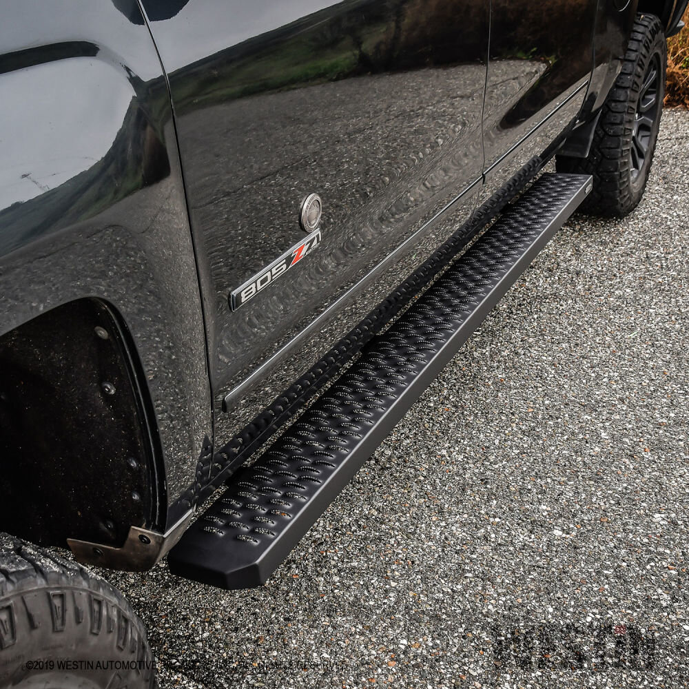
Inspect the complete underside before drilling. Powered steps need extra clearance for arms, pivots, linkages, motors, wiring, and their full travel. Fixed boards still have bracket fasteners, drain paths, seams, and vehicle lift points to avoid. Follow the light and board manufacturers’ drilling instructions; do not drill the truck body, structural bracket, or board extrusion merely because the top surface looks clear.
Route And Terminate Wiring For Road Exposure
Disconnect power according to the vehicle and accessory instructions before permanent work. Route the fused supply through automotive split loom or equivalent abrasion protection. Follow existing protected harness routes where appropriate, but do not tape the new circuit to hot exhaust components, brake or fuel lines, steering parts, suspension travel, driveshafts, sharp flanges, or service and lifting points.
Use proper grommets wherever wiring passes through metal. Support the loom at short, regular intervals with temperature- and UV-suitable retainers so it cannot sag or rub. Leave controlled service loops at moving boards and connectors, without creating a loop that can snag. Route connectors with drip protection and avoid low pockets that collect water.
For exterior splices, use sealed automotive connectors or correctly crimped adhesive-lined heat-shrink terminals rated for the wire and environment. Do not twist wires together, use household wire nuts, or rely on electrical tape as the primary seal. A good crimp uses the specified tool and passes a firm pull test before heat shrinking. Label the fuse and relay so a later technician knows the circuit is aftermarket.
Make A Reliable Ground Connection
A dedicated negative return to an approved distribution or battery point is often easier to validate than an improvised body ground. If the accessory instructions permit a chassis ground, use a documented point with clean metal contact, suitable terminal hardware, corrosion protection, and no interference with factory grounds. Do not ground through a running-board hinge, painted bracket, self-drilling screw, or corroded rocker metal.
Measure voltage at the lamps while they are operating. A significant difference between source voltage and lamp voltage indicates resistance in the positive or return path. Correct the connection or conductor size instead of installing a larger fuse.
Test The Installation Before Road Use
- Confirm the source fuse, relay, connectors, loom, and supports match the documented circuit plan.
- Test every intended trigger: unlock, each door, lock, timeout, auxiliary switch, ignition state, and manual override if fitted.
- Operate powered boards through several complete cycles while watching the harness and service loops.
- Check for flicker, delayed shutoff, warning messages, battery draw after timeout, hot connectors, or voltage drop.
- Inspect from outside at night to ensure the lamps do not glare, flash, or obscure required vehicle lighting.
- Reinspect mounting, chafe points, and seals after the first wet drive and again after winter exposure.
| Symptom | Likely area to inspect | Do not do |
|---|---|---|
| Lights flicker or glow faintly | PWM/module trigger, backfeed, interface, or ground | Add random resistors without calculating heat and load |
| Fuse opens immediately | Short, reversed polarity, pinched wire, or incorrect wiring | Install a larger fuse |
| One side is dim | Connector resistance, conductor length, or poor return | Assume the LED strip is the only possible fault |
| Battery drains | Relay state, always-hot trigger, module wake-up, or manual switch | Leave the truck unattended until measured |
| Powered board catches loom | Routing and service-loop geometry | Secure wiring to a moving arm |
When To Use An Automotive Electrician Or Upfitter
Professional installation is the sensible choice when factory wiring diagrams are unavailable, the courtesy signal is module-controlled, the truck has powered steps, auxiliary outputs require configuration, corrosion is present, or the route crosses crowded underbody areas. Ask the installer for the circuit diagram, fuse location and rating, wire specification, connector system, trigger method, and warranty before work begins.
The same fitment discipline used in GarageSanctum’s Ram running-board installation guide applies here: exact truck configuration comes before drilling. For powered steps, review the AMP PowerStep planning guide. The guides to running-board attachment methods and choosing a qualified installer cover the mechanical side.
Source Notes
- Ram Body Builder auxiliary-switch information illustrates why connection points and output details must be checked against the exact truck documentation.
- Stellantis 2019-2022 Ram 1500 SSV Upfitter Guide provides an official example of model-specific electrical and upfitting guidance.
- NHTSA interpretation on supplemental lamps discusses the requirement that additional lighting not impair required lighting equipment.
- NHTSA interpretation on auxiliary lighting notes the role of state regulation in auxiliary-lamp use.