NPT tap drills are larger than many readers expect because NPT is a tapered pipe thread, not a straight machine thread. Use the table below as a starting reference for common cutting taps, then confirm the hole size, thread depth, and inspection method in the instructions for the exact tap and material.
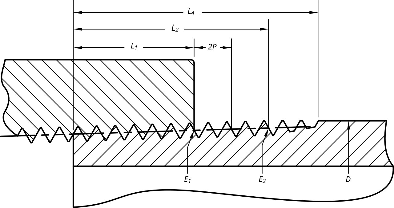
NPT thread dimensions, adapted from Phillip.toone’s NPT Dimensions diagram on Wikimedia Commons. Licensed CC BY-SA 4.0; the image was converted to a flattened JPEG for this article.
NPT tap drill size chart
The following chart uses the NPT/NPTF drill recommendations published by Allied Machine. Allied marks the values as applying without a taper reamer. The metric column is a conversion from the decimal-inch value and is rounded to two decimal places; it is not a substitute for a metric drill-size recommendation.
| NPT size | TPI | Recommended drill | Decimal inch | Approx. mm | Source |
|---|---|---|---|---|---|
| 1/16-27 | 27 | C | 0.242 | 6.15 | Allied Machine NPT chart |
| 1/8-27 | 27 | Q | 0.332 | 8.43 | Allied Machine NPT chart |
| 1/4-18 | 18 | 7/16 | 0.4375 | 11.11 | Allied Machine NPT chart |
| 3/8-18 | 18 | 9/16 | 0.5625 | 14.29 | Allied Machine NPT chart |
| 1/2-14 | 14 | 45/64 | 0.7031 | 17.86 | Allied Machine NPT chart |
| 3/4-14 | 14 | 29/32 | 0.9063 | 23.02 | Allied Machine NPT chart |
| 1-11 1/2 | 11.5 | 1-9/64 | 1.1406 | 28.96 | Allied Machine NPT chart |
| 1 1/4-11 1/2 | 11.5 | 1-31/64 | 1.4844 | 37.70 | Allied Machine NPT chart |
| 1 1/2-11 1/2 | 11.5 | 1-23/32 | 1.7188 | 43.66 | Allied Machine NPT chart |
| 2-11 1/2 | 11.5 | 2-7/32 | 2.2188 | 56.36 | Allied Machine NPT chart |
These are starting values for conventional cutting taps. Allied’s chart also lists NPTF with the same drill column for these sizes. For larger pipe taps, check the tap maker’s chart instead of extending this table by guesswork.
How to read an NPT size
The fraction in an NPT designation is a nominal pipe size. It is not the outside diameter of the male thread and it is not the diameter of the hole you should drill. For example, a 1/2 NPT thread has 14 threads per inch and a male outside diameter close to 0.84 inch at the reference location. The nominal 1/2 label comes from the historical pipe-size system, not from a direct measurement of the thread.
Use both the nominal size and the TPI when identifying a fitting. Several NPT sizes have similar thread pitches, and a measurement of outside diameter alone can lead to the wrong tap.
For a broader pipe-dimension reference, see the pipe size chart in millimeters and inches. That page covers nominal pipe size, outside diameter, DN, and Schedule 40 dimensions. This page is about making an NPT internal thread, so its drill values should not be substituted for a pipe-wall sizing table.
Why NPT needs a different workflow
NPT is a tapered thread. The standard thread form uses a 60-degree profile and a taper of 1 in 16 on diameter, commonly described as 3/4 inch per foot. Vermont Gage describes NPT as a tapered pipe thread and warns that NPT, NPTF, and other gaging systems should not be treated as interchangeable.
That taper is what allows a correctly made joint to tighten as the male and female threads engage. It also means the finished fit depends on more than the first drilled diameter. The tap must cut far enough to create the required engagement, but the part must still meet the intended gauge or fitting requirement.
The diagram above shows why an NPT thread cannot be treated exactly like a 1/4-20 or M10 straight thread. A straight tap produces a constant thread diameter. An NPT tap produces a tapered internal thread, so the position of the thread along the hole affects the fit.
Drill depth is not tapping depth
For a through hole, drill far enough for the tap to pass and for chips to escape. For a blind hole, drill deeper than the required finished thread length. Reserve room for the drill point, the tap chamfer, chips, and the unthreaded portion at the bottom of the hole.
Do not publish or follow one universal “NPT tapping depth.” The usable depth varies with nominal size, tap style, tap chamfer, material, hole geometry, and the fitting or gauge used for inspection. A short-chamfer bottoming tap and a standard taper tap do not produce the same result at the same depth.
A practical workflow is:
- Identify the exact thread: NPT, NPTF, NPS, or another standard.
- Select the tap manufacturer’s drill recommendation for that tap.
- Drill the hole deep enough for the required thread plus clearance for the tool.
- Chamfer the entrance lightly so the tap starts squarely and does not damage the first thread.
- Use suitable cutting fluid and reverse the tap often enough to control chips for the material.
- Check the finished thread with the specified gauge or the actual mating fitting. Do not force a fitting to compensate for a hole that is too shallow or a thread that is out of tolerance.
NPT vs. NPTF
NPT is the common National Pipe Taper thread. It normally relies on a sealant, tape, or a compatible sealing compound to close the helical leak path. NPTF is the Dryseal version. Its geometry and inspection requirements are intended to reduce leakage through thread interference, but the two designations are not permission to use any tap, gauge, or sealant interchangeably.
Allied lists common NPT and NPTF tap drills together, but that does not mean their finished parts have identical acceptance criteria. Vermont Gage lists separate NPT and NPTF gages and explains that NPTF inspection uses different gaging requirements. Confirm the thread designation on the drawing, fitting, or equipment documentation before choosing the tap.
Material and tap-maker differences
A chart value is a reference, not a guarantee of a perfect hole in every material. Cutting force, elasticity, chip control, tap coating, tap geometry, coolant, machine rigidity, and the desired thread percentage can change the best starting hole. A harder material may need a different recommendation than a soft aluminum or plastic part. Forming taps require a different hole-size method from cutting taps and should never use this cutting-tap table automatically.
If the exact tap documentation conflicts with a generic chart, follow the exact tap documentation. For example, Allied’s technical guide gives NPT-specific drill data and distinguishes nominal drill diameter from the probable hole size after oversize. That distinction matters when the finished thread must meet a gauge or a controlled fit.
Sealant and inspection notes
Sealant is part of the joint design, not a way to repair an incorrectly cut thread. Use a sealant compatible with the fluid, pressure, temperature, and material. Keep sealant out of systems where loose material can damage valves, regulators, sensors, or filters.
For critical work, inspect the thread with the specified NPT or NPTF plug or ring gauge. Vermont Gage explains that an NPT L1 gauge does not by itself inspect every possible engagement length. A fitting that seems to tighten by hand is not a complete dimensional inspection.
For related references, see the compressed-air pipe size and CFM chart and the tap and die set guide. Keep straight-thread drill references separate from this NPT table rather than mixing the two systems.
Sources and update note
- Allied Machine: National Pipe Threads tap-drill chart
- Allied Machine: recommended cutting data and NPT drill information
- Vermont Gage: NPT taper pipe thread inspection
- Vermont Gage: NPT and NPTF thread gages
- ICS Cutting Tools: reference resources
Recheck the tap manufacturer’s chart before machining a production part. Manufacturer recommendations and product documentation can change.