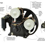
Two-stage compression with effective intercooling can reduce the ideal work needed to reach a given air pressure. That principle does not create a universal horsepower-to-CFM conversion. Pressure ratio, inlet conditions, cooling, mechanical losses, and the way airflow is reported all affect the comparison.
The table below is a calculated thermodynamics example, not a list of compressor ratings. Use it to understand why staging and cooling matter. For buying equipment or selecting a motor, use the exact compressor’s measured delivery, electrical requirements, duty limits, and manufacturer documentation.
Calculated ideal power per inlet CFM
These examples use an inlet pressure of 101.325 kPa absolute, approximately standard atmospheric pressure. Air is modeled as an ideal gas with a specific-heat ratio of 1.4. Both stages are ideal isentropic compression steps, have equal absolute-pressure ratios, and are separated by perfect intercooling back to inlet temperature.
| 90 | 0.1689 | 0.1453 | 13.9 |
|---|---|---|---|
| 125 | 0.2027 | 0.1703 | 15.9 |
| 175 | 0.2417 | 0.1980 | 18.1 |
3 rows
Scroll horizontally to view all columns.
The calculation excludes pressure losses, mechanical friction, motor losses, and accessory loads. Inlet CFM means actual volume flow at the stated inlet conditions. Do not relabel it as an arbitrary manufacturer’s SCFM or delivered-air rating without confirming that rating’s reference conditions.
Use absolute pressure in the ratio
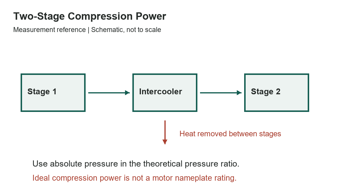
A gauge normally measures pressure above the surrounding atmosphere. Absolute pressure includes atmospheric pressure. To obtain the overall compression ratio, add the assumed atmospheric pressure to the gauge discharge pressure, then divide by the absolute inlet pressure.
For example, a discharge of 125 psig is not a ratio of 125 divided by zero. Under the inlet assumption used here, its absolute discharge pressure is about 139.7 psia and the overall pressure ratio is about 9.50. Changing inlet pressure changes that ratio and the calculated work.
Why cooling between stages changes the result
Compression raises the air temperature in this ideal model. Intercooling removes heat before the next stage. Returning the air to the original inlet temperature reduces the second stage’s ideal work compared with carrying the full temperature rise into the next compression step.
The two-stage column assumes perfect intercooling and an equal pressure-ratio split. Real intercoolers do not necessarily return air to inlet temperature, and real stages have losses and operating constraints. The percentage column describes only the difference between the two stated ideal models. It is not a promised electricity saving for a compressor in your garage.
The equations behind the table
Let PR be the overall absolute-pressure ratio, k the specific-heat ratio, p1 the absolute inlet pressure, and Q1 the inlet volume flow. The single-stage ideal power is k/(k-1) multiplied by p1Q1 and by [PR raised to ((k-1)/k), minus one]. Use consistent pressure, flow, and power units.
For two equal-ratio stages with perfect intercooling, multiply k/(k-1) by 2p1Q1 and by [PR raised to ((k-1)/(2k)), minus one]. The calculations use 0.0004719474432 cubic meters per second for one inlet CFM, then convert watts to mechanical horsepower using approximately 745.6999 watts per HP.
The work scales with inlet flow within these assumptions. Multiplying a table value by an inlet-CFM figure produces another ideal-model result, not an approved motor rating. Do not add a guessed percentage and treat that as a complete equipment design.
What to compare on actual equipment
Compare delivered airflow at the pressure your tools require, with the rating method and reference conditions identified. Also check package input power or electrical requirements, duty limitations, cooling requirements, and the manufacturer’s installation instructions. A large receiver does not establish sustained compressor delivery.
CAGI’s performance-verification program supplies independently checked data for covered rotary compressors and refrigerated dryers. That program’s scope should not be extended to every small reciprocating garage compressor. When your exact machine is outside the program, obtain its own documented performance and operating limits.
Use the right guide for the decision
This page explains ideal compression work. The two-stage compressor overview addresses the equipment category. The compressor-sizing guide covers practical demand, and the compressed-air pipe chart concerns distribution rather than motor sizing.
References
NASA Glenn’s compressor thermodynamics explanation provides the ideal pressure-ratio and work relationship; the two-stage values here are independently calculated from that relationship. See CAGI’s performance-verification information for the scope of measured equipment comparisons.