Quick answer: To splice LED light strips safely, match the strip voltage, width, pin count, polarity, and waterproof rating before connecting anything. Use solder for the most reliable permanent splice, or use solderless strip connectors for easier low-voltage indoor projects. Test the splice before mounting it, and add strain relief so the copper pads are not carrying the weight of the wire.
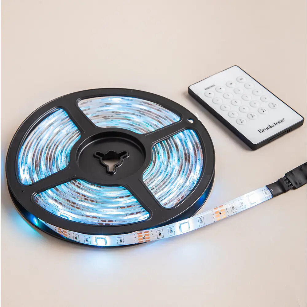
Before You Splice: Match The Strip
Most bad LED strip splices happen before the first wire is connected. A connector for a 10 mm RGB strip will not fit an 8 mm single-color strip. A 12V strip should not be mixed with a 24V strip. Waterproof silicone coating changes the connector choice and usually needs trimming or a special connector.
| Check | What to match | Why it matters |
|---|---|---|
| Voltage | 12V with 12V, 24V with 24V | Wrong voltage can damage strips or make them dim |
| Strip width | 8 mm, 10 mm, 12 mm, or product-specific | Connector contacts must land on copper pads |
| Pin count | 2-pin, 3-pin, 4-pin RGB, 5-pin RGBW, addressable pads | Wrong pin count means missing colors or no light |
| Polarity | Positive to positive, negative/color channel to matching pad | Reversed polarity prevents operation and may damage electronics |
| Waterproof coating | Bare, silicone-coated, or IP-rated strip | Coating may block connector contacts |
| Current load | Connector and wire amp rating | Underrated connectors can heat or fail |
Solder Vs Solderless Connectors
Solderless connectors are convenient, especially for short indoor accent runs. Solder is usually better for permanent installs, tight spaces, high-current runs, vehicles, vibration, or places where a loose connection would be hard to fix later.
| Method | Best for | Tradeoff |
|---|---|---|
| Soldered splice | Permanent installs, corners, wire leads, higher reliability | Needs soldering skill and heat-shrink/insulation |
| Clip-on strip connector | Fast indoor connections and testing layouts | Can loosen if pulled or installed on dirty/coated pads |
| Strip-to-wire connector | Jumping gaps, cabinet/ceiling transitions | Must match strip width and pin count |
| Corner connector | 90-degree turns without bending strip sharply | Can create voltage drop or color-channel issues if low quality |
| Terminal block/Wago style after pigtails | Serviceable wiring junctions away from strip pads | Still needs a reliable strip-to-wire connection first |

Safe Splicing Steps
- Unplug the LED strip power supply before cutting or splicing.
- Cut only on the marked cut lines.
- Expose clean copper pads; remove silicone coating only where the connector or solder needs contact.
- Match polarity and channel labels before connecting.
- For solderless connectors, slide the strip fully under the contacts and close the latch evenly.
- For soldered splices, tin the pads and wires, solder quickly, and avoid overheating the strip.
- Insulate the splice with heat shrink, electrical tape, or an enclosure as appropriate.
- Test before sticking the strip down permanently.
- Add strain relief so wire movement does not pull on the copper pads.
Polarity And RGB Pin Matching
Single-color strips usually have positive and negative pads. RGB strips commonly have a shared positive plus red, green, and blue channels. RGBW strips add a white channel. Addressable strips add data direction and often have arrows showing signal flow. Do not assume wire colors are universal; follow the printed pad labels.
| Strip type | Common pads | Splice caution |
|---|---|---|
| Single-color | + and – | Reverse polarity usually means no light |
| CCT tunable white | + plus warm/cool channels | Channels must match controller output |
| RGB | + / R / G / B | Wrong channel order swaps colors |
| RGBW | + / R / G / B / W | Needs 5-pin connector/controller path |
| Addressable | + / data / – or + / data / clock / – | Data direction and voltage must match |

Voltage Drop And Power Injection
Splicing strips end-to-end can make the far end dimmer or change color, especially on long 12V runs. If the run is long or high wattage, feed power from both ends or add power injection points instead of forcing all current through the first strip section.
| Symptom | Likely cause | Better fix |
|---|---|---|
| Far end is dimmer | Voltage drop across strip copper | Use shorter runs, 24V strip, or power injection |
| White turns pink/yellow at far end | Uneven channel voltage drop | Power from both ends or inject power mid-run |
| Connector gets warm | Too much current or poor contact | Use better connector, solder, or split the load |
| Only one color works after splice | Wrong RGB/RGBW channel alignment | Recheck pad labels and connector orientation |
| Strip flickers when touched | Loose connector or no strain relief | Redo splice and secure wire/strip mechanically |
Related GarageSanctum Guides
- Hide LED strips on a ceiling
- LED wattage explained
- LED flickering troubleshooting
- LED light colors explained
- How long LED lights last
Source Notes
- DigiKey LED strip lighting design guide discusses strip power, voltage, current, controllers, and supply sizing considerations.
- Flexfire LED solderless connector guide emphasizes matching polarity and aligning positive markings through the strip and power supply.
- LEDSupply strip connector guide compares 2-pin and 4-pin connector use cases and notes soldering as the more reliable option when appropriate.
- Flexfire voltage drop guide explains splitting long runs and adding parallel power feeds to reduce voltage drop.