Duct Sizing Chart CFM
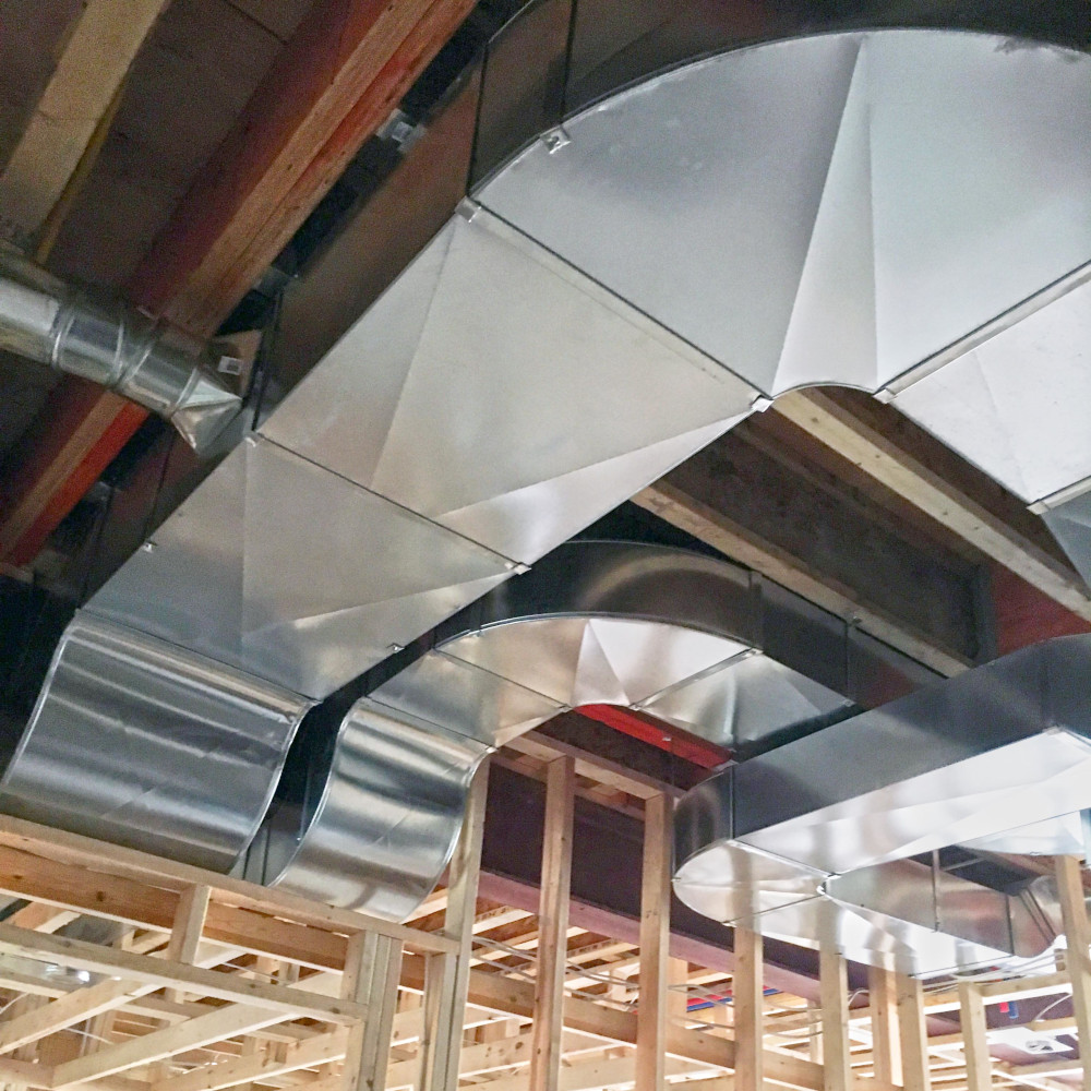
Quick answer: duct size depends on CFM, duct type, friction rate, equivalent length, fittings, static pressure, and acceptable noise. A quick field chart may put 8-inch round metal duct around 180 CFM, 10-inch around 300 CFM, and 12-inch around 480 CFM, but final HVAC design should use a Manual D / ductulator calculation.
Round Duct Size Chart
| Round duct size | Approx. metal duct CFM | Approx. flex duct CFM | Typical note |
|---|---|---|---|
| 5 in | 50 CFM | 50 CFM | Small branch run |
| 6 in | 85 CFM | 75 CFM | Small room branch |
| 7 in | 125 CFM | 110 CFM | Medium branch |
| 8 in | 180 CFM | 160 CFM | Common branch/trunk transition |
| 9 in | 240 CFM | 225 CFM | Large branch |
| 10 in | 325 CFM | 300 CFM | Small trunk |
| 12 in | 525 CFM | 480 CFM | Trunk line |
| 14 in | 750 CFM | 700 CFM | Trunk line |
| 16 in | 1,200 CFM | 1,000 CFM | Main trunk |
| 18 in | 1,500 CFM | 1,300 CFM | Main trunk |
| 20 in | 2,000 CFM | 1,700 CFM | Main trunk |
Rectangular Duct Size Examples
| Design airflow | Example rectangular sizes | Approx. round equivalent | Note |
|---|---|---|---|
| 100-150 CFM | 8 x 6 in, 10 x 4 in | 6-7 in round | Small branch |
| 200-300 CFM | 10 x 8 in, 12 x 6 in | 8-10 in round | Medium branch |
| 400-500 CFM | 14 x 8 in, 16 x 8 in | 11-12 in round | Large branch/small trunk |
| 700-800 CFM | 18 x 10 in, 20 x 8 in | 14 in round | Trunk duct |
| 1,000-1,200 CFM | 20 x 12 in, 24 x 10 in | 16 in round | Main trunk |
Before Using A Duct Size Chart
- Account for elbows, takeoffs, registers, filters, dampers, and flex duct compression.
- Keep air velocity reasonable to avoid noise.
- Use a duct calculator or Manual D process for final design.
- Check total external static pressure against the blower’s rated airflow.
Source Notes
CFM ranges were checked against field duct charts and friction-loss references including HVACDirect’s field duct sizing chart, Thermaflex air-flow/friction charts, and Engineering ToolBox duct friction references. Treat the table as an estimate, not a design stamp.